Remotely-activated vertebroplasty injection device

a technology of injection device and vertebroplasty, which is applied in the field of remote activation of vertebroplasty injection device, can solve the problems of bone loss density and strength, increased risk of x-ray radiation exposure, so as to improve the safety of clinicians, reduce pressure concerns, and improve control

Active Publication Date: 2009-10-29
DEPUY SYNTHES PROD INC +1
View PDF101 Cites 29 Cited by
  • Summary
  • Abstract
  • Description
  • Claims
  • Application Information

AI Technical Summary

Benefits of technology

[0009]In operation, an injection pump is anchored to the patient and a hollow bone needle extends from the exit opening of the pump for transferring the fluorescent probe material into the vertebral body of the patient. The needle can be straight or angled. By anchoring the pump directly to the patient, problems typically associated with extension tubes are eliminated.
[0010]Such embodiments improve clinician safety because the pump is remotely operated at a safe distance outside the range of the fluoro field. Furthermore, the pump can be anchored directly to the patient, thereby avoiding the use of extension tubes and thereby improving control and reducing pressure concerns.

Problems solved by technology

Osteoporosis causes bone to lose density and strength resulting in porous, weak bones especially susceptible to fracture.
It is well known that excessive exposure to x-ray radiation is dangerous and even cancer-causing.
A disadvantage of such injection devices is that the extension tube produces a pressure drop, making it more difficult to deliver the bone cement through the tube.
However, such mechanisms typically reduce the natural feedback or “feel” of the injection device, resulting in a number of pressure concerns.
For example, the lack of natural feedback can cause the clinician to inadvertently leak bone cement into the surrounding tissue or the spinal cord itself, resulting in a number of serious health risks.
Furthermore, the additional length of the tube makes such injection devices susceptible to premature curing or hardening, resulting in the tube becoming clogged.

Method used


Image

  • Remotely-activated vertebroplasty injection device
  • Remotely-activated vertebroplasty injection device
  • Remotely-activated vertebroplasty injection device

Examples


Embodiment Construction

[0022]The foregoing and other objects, features and advantages of the invention will be apparent from the following more particular description of preferred embodiments of the invention, as illustrated in the accompanying drawings in which like reference characters refer to the same parts throughout the different views. The same number present in different drawings refers to the same item. The drawings are not necessarily to scale, emphasis instead being placed upon illustrating the principles of the invention.

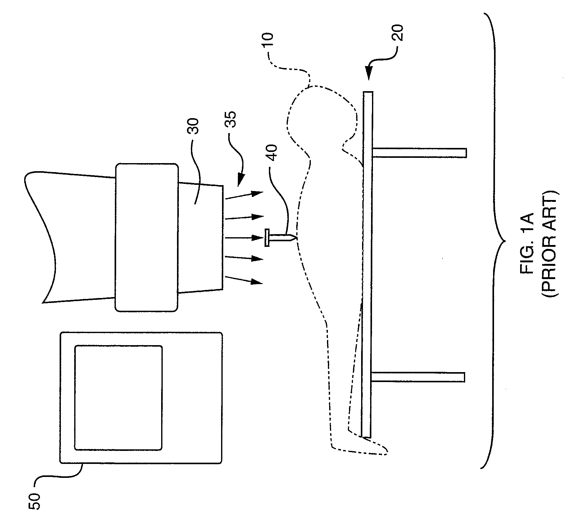
[0023]FIG. 1A is a diagram illustrating a general procedure for performing vertebroplasty. In this procedure, anesthetized patient 10 lies on operating table 20 in a downward-facing, horizontal position underneath x-ray machine 30, referred to as a fluoroscope.

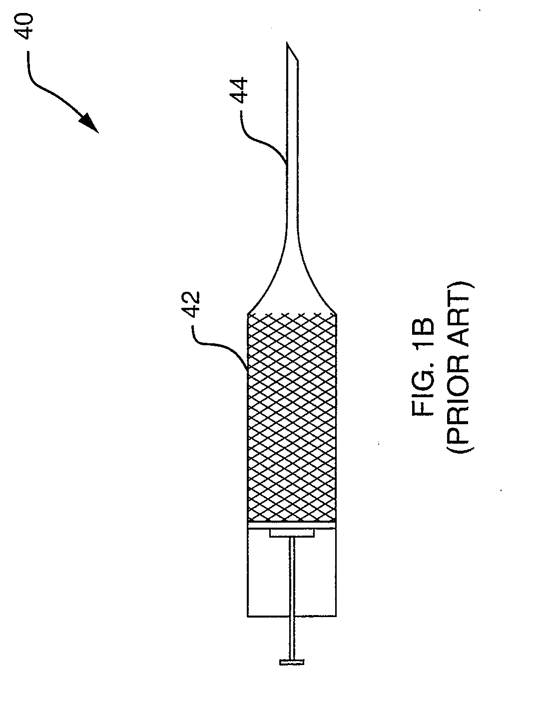
[0024]The clinician mixes the bone cement along with a flourescent probe to the consistency of a thin paste and prepares the resulting flourescent probe material for injection into the vertebral body through syringe 40, ...


PUM


Abstract

A remotely-activated injection device for use in vertebroplasty is provided to inject a flourescent probe material into a patient. The injection device includes a pump defining an injection chamber having an exit opening; an actuator; and a cable having a first end coupled to the actuator, and a second end remotely engaging the pump. The actuator remotely controls the pump by responsive movement of the cable to thereby cause injection of a flourescent probe material from the injection chamber of the pump through the exit opening to the patient.

Description

RELATED APPLICATIONS[0001]This application is a continuation of U.S. patent application Ser. No. 10 / 405,113 to DiMauro et al., filed on Mar. 31, 2003, and entitled “Remotely-Activated Vertebroplasty Injection Device,” which application is incorporated herein by reference in its entirety.BACKGROUND OF THE INVENTION[0002]Over 700,000 vertebral fractures occur each year in the United States. Eighty-five percent of these vertebral fractures are associated with osteoporosis. Osteoporosis causes bone to lose density and strength resulting in porous, weak bones especially susceptible to fracture.[0003]Vertebroplasty is a non-surgical procedure for combating the effects of osteoporosis and the like, in which a vertebral body is structurally reinforced using a special cement-like substance, or bone cement. A typical bone cement for use in vertebroplasty is called “polymethylmethacrylate acrylic cement” (PMMA). Vertebroplasty has been used in the treatment of vertebral lesions (hemangoma), sp...

Claims


Application Information

Patent Timeline
Patent Type & Authority Applications(United States)
IPC IPC(8): A61B17/58A61M1/00A61B17/88A61F2/00A61F2/46A61F2/48
CPCA61B17/8822A61F2/4601A61F2002/3008A61F2250/0098A61F2002/48A61F2220/0025A61F2002/30523A61F2/48
Inventor DIMAURO, THOMAS M.CROMBIE, JOHNPELLEGRINO, RICHARDREYNOLDS, MARTIN A.
Owner DEPUY SYNTHES PROD INC
Why Eureka
Try Eureka