
Status transition test support device, status transition test support method, and recording medium

a technology of status transition test and support device, which is applied in the direction of instruments, error detection/correction, computing, etc., can solve the problems of difficult for the test performer to find such a combination, difficult for the test performer to identify, and difficult to efficiently execute the status transition tes

Inactive Publication Date: 2009-10-29
DAINIPPON SCREEN MTG CO LTD
View PDF9 Cites 10 Cited by
  • Summary
  • Abstract
  • Description
  • Claims
  • Application Information

AI Technical Summary

Benefits of technology

[0008]Therefore, an object of the present invention is to provide a status transition test support device for supporting efficient execution of the status transition test.
[0019]According to this configuration, a test path to be executed as the status transition test is generated by the test path generation portion based on “combinations of internal status and event” inputted into cells (combination information cells) of the status transition table by the operator. Thus, it is possible to significantly shorten the time conventionally required for test path generation. In addition, when the status transition test is executed, a test result for each test case included in the test path and information for specifying the order of test execution (execution order specification information) are recorded to the test result holding portion based on input by the operator. Thus, it is possible to determine in which test path and up to which test case has already been executed based on data held by the test result holding portion.
[0021]According to this configuration, a combination information cell associated with the next test case to be executed (hereinafter, referred to as a “test cell”) is highlighted during execution of the status transition test. Thus, it is possible to eliminate the necessity for the operator to find the test cell by him / herself, resulting in quick execution of the status transition test.
[0023]According to this configuration, any test path including an unexecuted test case is displayed as a candidate for the next test path to be executed during execution of the status transition test. Thus, it is possible to eliminate the necessity for the operator to find by him / herself the test path to be executed, resulting in quick execution of the status transition test.
[0028]According to this configuration, when there is any test case with test result “error (fail)”, the test execution procedure for replicating the error is displayed. Therefore, the operator can perform error replication more readily. Thus, it is possible to readily trace the cause of the error, thereby achieving efficient system development.
[0030]According to this configuration, the progress of the status transition test is displayed. Thus, it is possible to readily manage the progress of system development including the status transition test.

Problems solved by technology

When the designer of a system differs from the performer of the status transition test, it is difficult for the test performer to identify a “combination of system internal status and event” with which to start the test.
Even after the test is started, it is still difficult for the test performer to find such a combination.
Also, in the case of a system in which a variety of types of status transition can occur, it is not easy to figure out by which route (test path to be described later) the test has been executed, and therefore it is difficult to efficiently execute the status transition test.
Furthermore, when an error occurs during the test, it is difficult to figure out the procedure for replicating the error.
Also, Japanese Laid-Open Patent Publication No. 2006-112852 mentions creation of the test scenario, which, however, does not mean that the status transition test is efficiently executed.

Method used


Image

  • Status transition test support device, status transition test support method, and recording medium
  • Status transition test support device, status transition test support method, and recording medium
  • Status transition test support device, status transition test support method, and recording medium

Examples


Embodiment Construction

[0087]Hereinafter, an embodiment of the present invention will be described with reference to the accompanying drawings.

[0088]

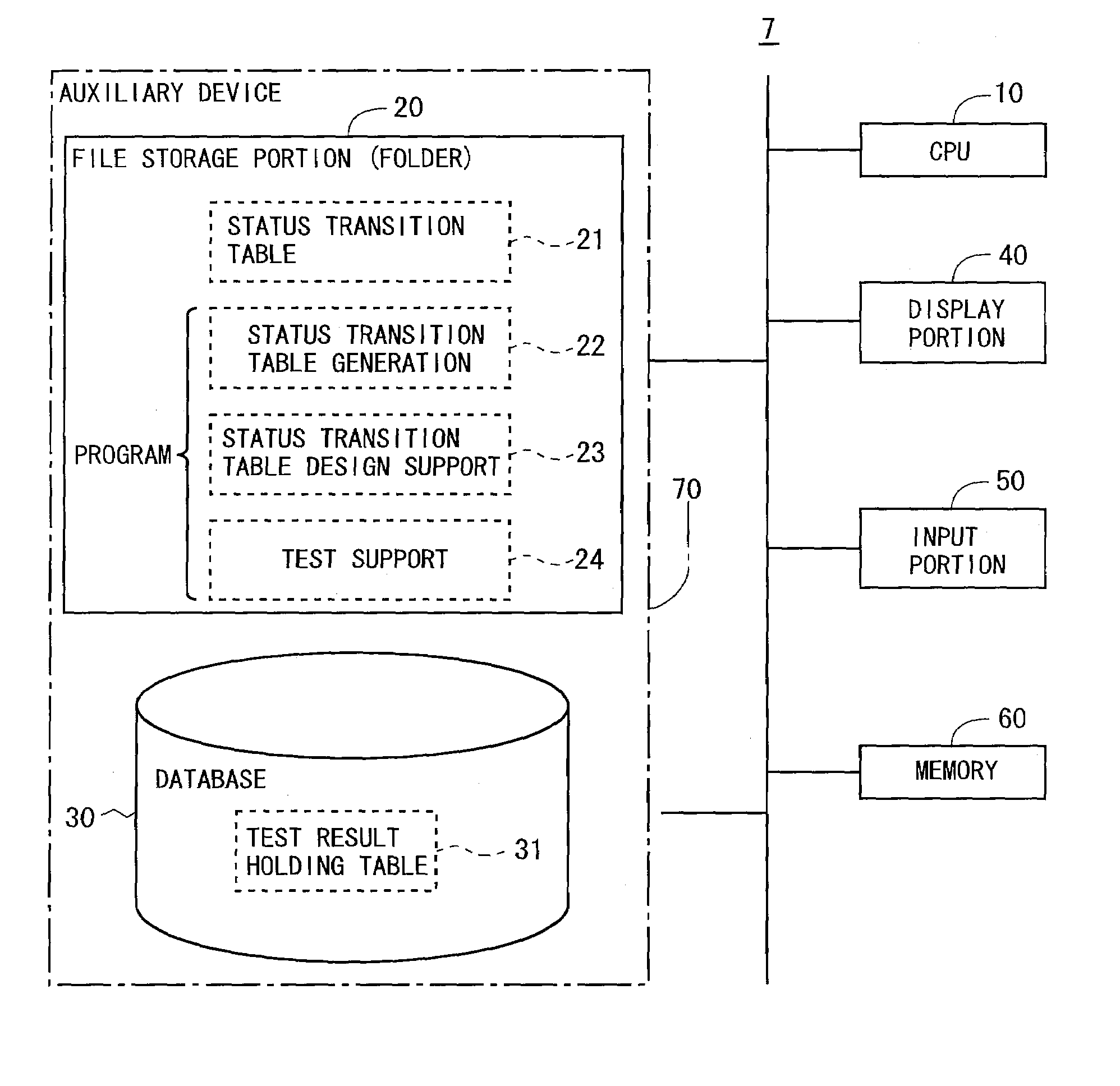
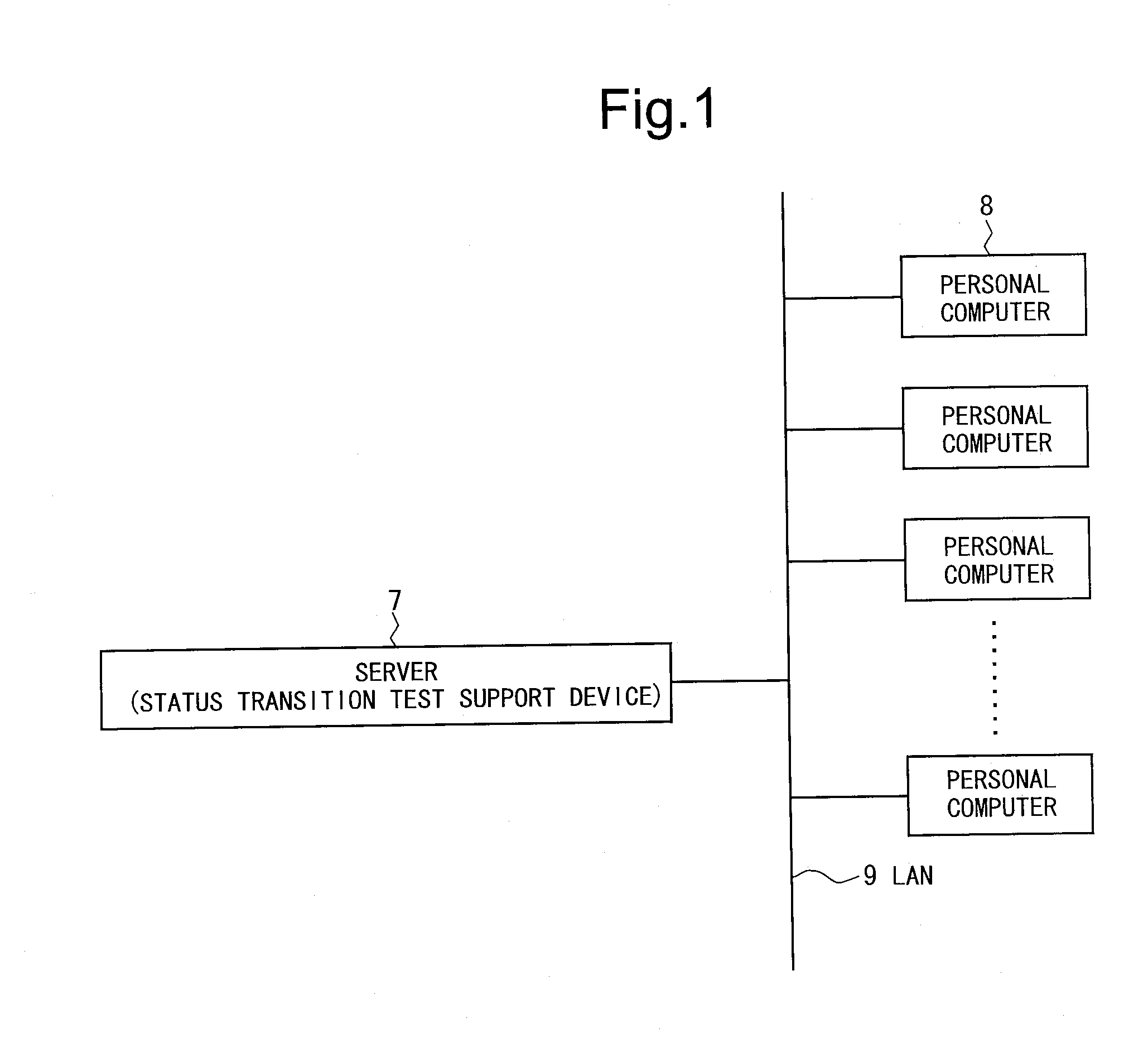
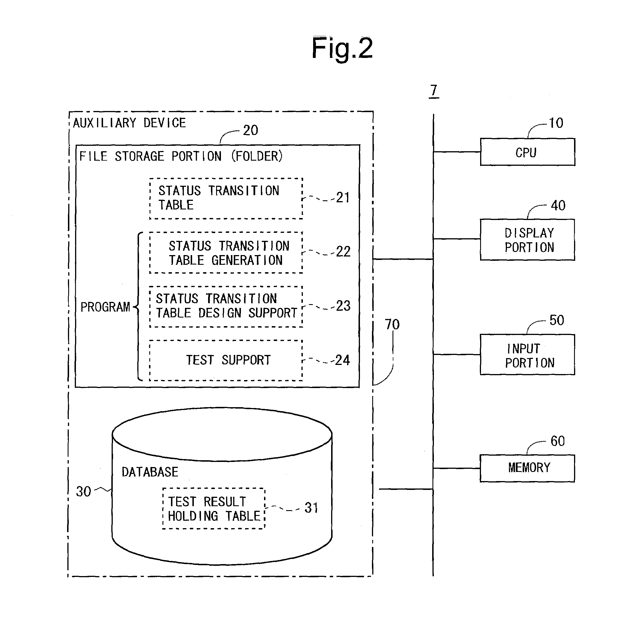
[0089]FIG. 1 is a hardware configuration diagram for an entire system in an embodiment of the present invention. This system includes a server 7 and a plurality of personal computers 8. The server 7 and each personal computer 8 are interconnected via a LAN 9. In the personal computer 8, for example, programming tasks for software system development, as well as test execution, are performed. The server 7 executes processing in accordance with requests from the personal computers 8, and stores files, databases, etc., which, for example, can be commonly referenced by the personal computers 8. In addition, the server 7 provides various functions for supporting execution of the status transition test. Note that programs to be described later (a status transition table generation program, a status transition table design support program, and a test support program)...


PUM


Abstract

A status transition table generation portion generates a status transition table containing combination information cells provided in the form of a matrix for describing information corresponding to combinations of internal status and event. In a status transition table design support portion, a test path generation portion generates a test path including a series of test cases to be executed as a status transition test, based on information accepted by an operation specification information input acceptance portion. In a test support portion, a test cell highlight portion highlights a combination information cell associated with the next test case to be executed, during execution of the status transition test, and a test result history, an error replication procedure, and test progress are displayed on a display portion.

Description

BACKGROUND OF THE INVENTION[0001]1. Field of the Invention[0002]The present invention relates to devices for supporting efficient software system design, development, maintenance, etc. More particularly, the invention relates to a status transition test support device for supporting efficient execution of a test (hereinafter, referred to as a “status transition test”) using a status transition table describing internal status transition of a system.[0003]2. Description of the Background Art[0004]Conventionally, for software system design or development, it is often the case that a status transition table describing internal status transition (change) of a system is created. The status transition table consists of a plurality of sections partitioned by vertical and horizontal lines (note that each section is referred to as a “cell”.). In the status transition table, each column (or each row) is associated with an internal status that may be taken by the system, while each row (or eac...

Claims


Application Information

Patent Timeline
IPC IPC(8): G06F11/263
CPCG06F11/263
Inventor MIYAI, KIYOTAKAKASUBUCHI, KIYOTAKAYAMAMOTO, HIROSHI
Owner DAINIPPON SCREEN MTG CO LTD
Learn More