Power producing device utilizing fluid driven pump

a technology of fluid-driven pumps and power producing devices, which is applied in the direction of electrical equipment, electrical storage systems, machines/engines, etc., to achieve the effects of minimal structural materials, efficient use of stored energy, and expansion of power output capacity

Inactive Publication Date: 2009-11-05
PLANT JR WILLIAM R
View PDF21 Cites 3 Cited by
  • Summary
  • Abstract
  • Description
  • Claims
  • Application Information

AI Technical Summary

Benefits of technology

[0009]According to the present invention, a device is provided which meets the aforementioned requirements and needs in the prior art. Specifically, the device according to the present invention provides an apparatus for efficiently using stored energy, for a range of demand and operating conditions, and uses minimal structural materials for a stored energy powered apparatus. Also, the apparatus can produce electricity when any of a plurality of electrical generators is disabled or cannot be used, and can be incrementally expanded in power output capacity.

Problems solved by technology

From the foregoing, it is seen that it is a problem in the art to provide a device meeting the above requirements.

Method used


Image

  • Power producing device utilizing fluid driven pump
  • Power producing device utilizing fluid driven pump
  • Power producing device utilizing fluid driven pump

Examples


Embodiment Construction

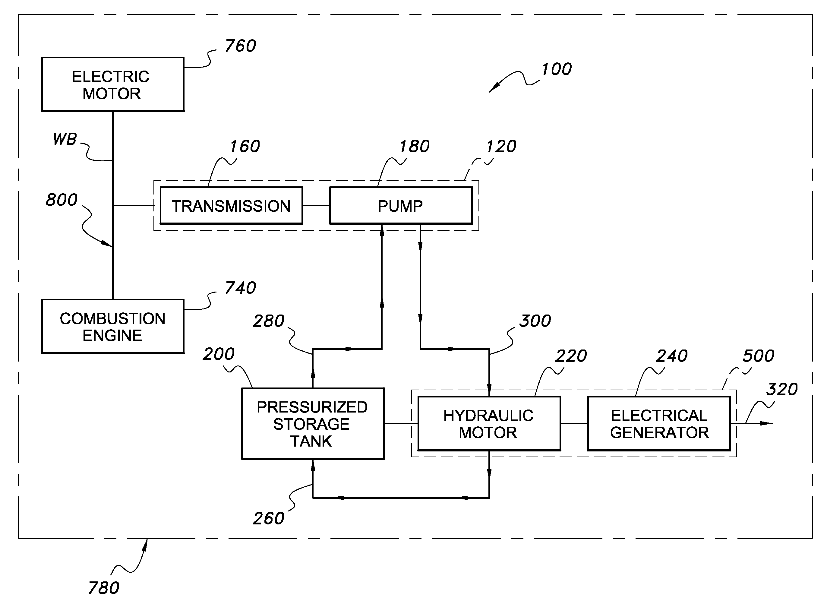
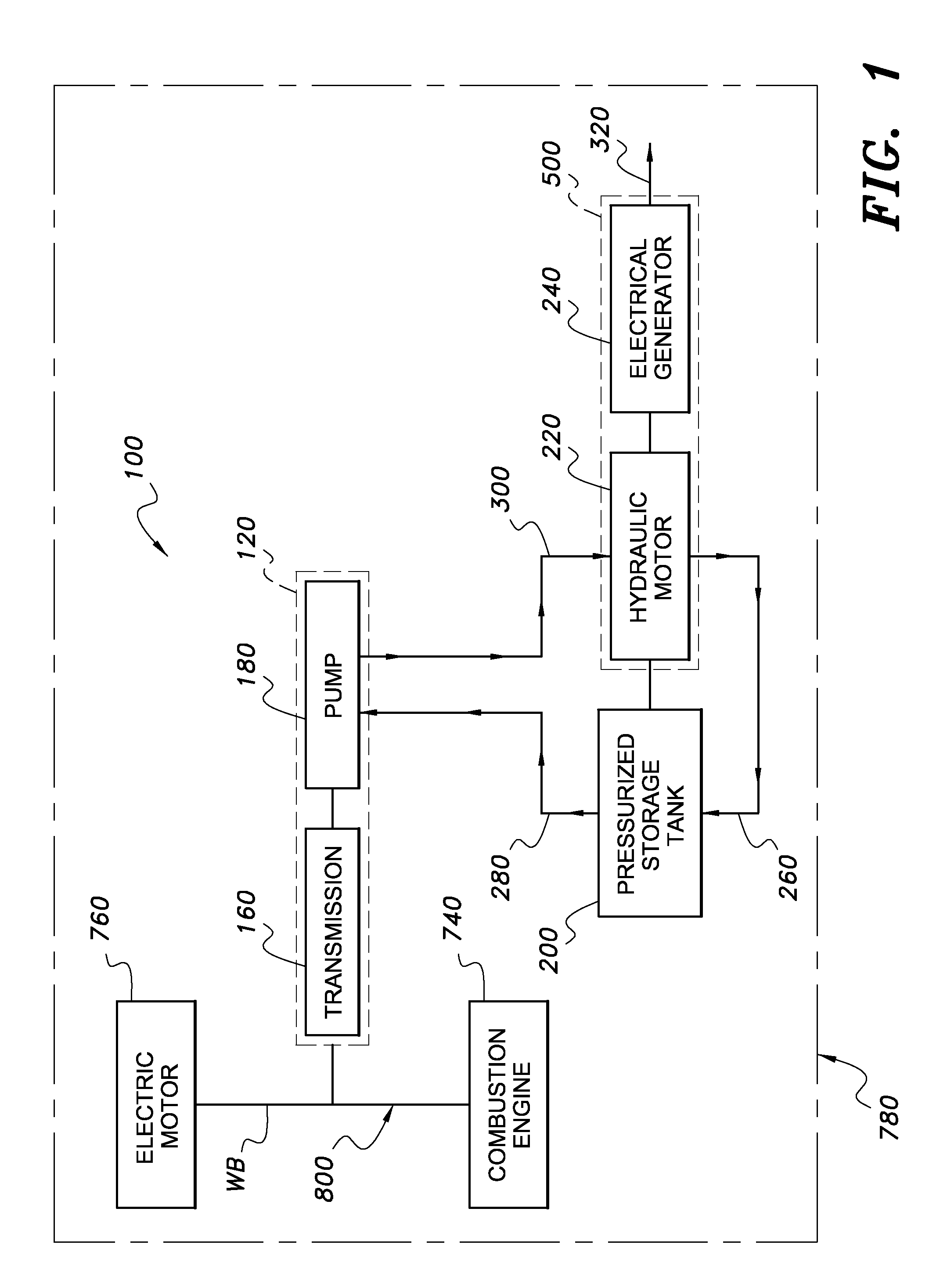
[0017]FIG. 1 is schematic side view of a power producing device 100 utilizing a hydraulic pump 180, the power producing device including a combustion engine 740 and an electric motor 760 connected to a dual drive transmission 800, and a housing 120. The dual drive transmission 800 has opposing shafts, with the electric motor 760 and the combustion engine 740 acting on the dual drive transmission 800 so as to drive the transmission 160. The entire assembly of elements shown in FIG. 1 is shown as enclosed by an enclosure 780. The enclosure 780 is a waterproof and sound reducing structure that can be custom designed to fit the environment it is to be utilized in. Examples of such an enclosure can include a log cabin for use at mountain resorts or municipalities, mini casino design, fiberglass or metal container for placement on the roof tops of high rise office and apartment complexes (such as those in New York City).

[0018]The combustion engine 740 produces power for rotating the dual ...


PUM


Abstract

A power producing device apparatus includes a combustion engine and an electric motor connected to a dual drive transmission, and a housing. The dual drive transmission has opposing shafts, with the electric motor and the combustion engine acting on the dual drive transmission so as to drive the transmission. The entire assembly is enclosed by an enclosure which is a waterproof and sound reducing structure that can be custom designed to fit an environment it is to be used in. Examples of such an enclosure can include a log cabin for use at mountain resorts or municipalities, mini casino design, fiberglass or metal container for placement on the roof tops of high rise office and apartment complexes.

Description

CROSS REFERENCE TO RELATED APPLICATIONS[0001]This application is a continuation-in-part of U.S. patent application Ser. No. 12 / 113,217, which was filed on May 1, 2008 and which is incorporated herein by reference in its entirety.STATEMENT REGARDING FEDERALLY SPONSORED RESEARCH OR DEVELOPMENT[0002]Not applicable.FIELD OF THE INVENTION[0003]The present invention relates generally to an apparatus for producing electrical power from stored energy. More particularly, this invention is directed to an apparatus for producing electrical power from stored energy using a plurality of generator sets arranged in stages.BACKGROUND OF THE INVENTION[0004]In U.S. Pat. No. 7,183,664 to McClintic, an advanced wind turbine design is shown which includes a wind powered rotary blade arrangement which powers a hydraulic pump. The pump pressurizes a hydraulic fluid which powers a hydraulic motor on the ground. The hydraulic motor powers an electrical generator, producing power.[0005]U.S. Pat. No. 4,496,84...

Claims


Application Information

Patent Timeline
Patent Type & Authority Applications(United States)
IPC IPC(8): F02D25/00
CPCF02D29/06Y02E60/15H02J15/006Y02E60/16
Inventor PLANT, JR., WILLIAM R.
Owner PLANT JR WILLIAM R
Why Eureka
Try Eureka