

Flexible electroluminescent capacitive sensor
a flexible, capacitive sensor technology, applied in semiconductor/solid-state device testing/measurement, semiconductor/solid-state device details, instruments, etc., can solve the problems of high cost, complicated electrical addressing required to drive both, and the extra material and other manufacturing costs of light-emitting devices with separate sensors
- Summary
- Abstract
- Description
- Claims
- Application Information
AI Technical Summary
Problems solved by technology
Method used
Image

Examples
Embodiment Construction
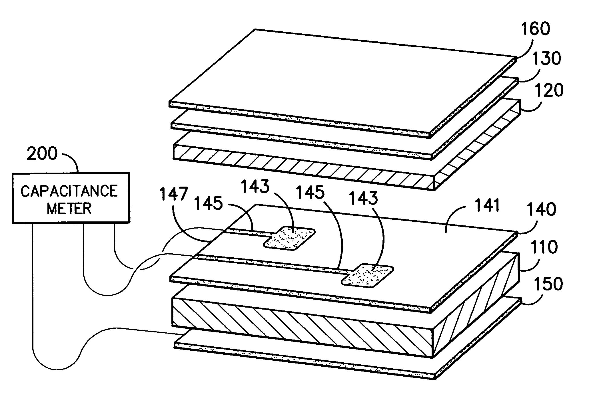
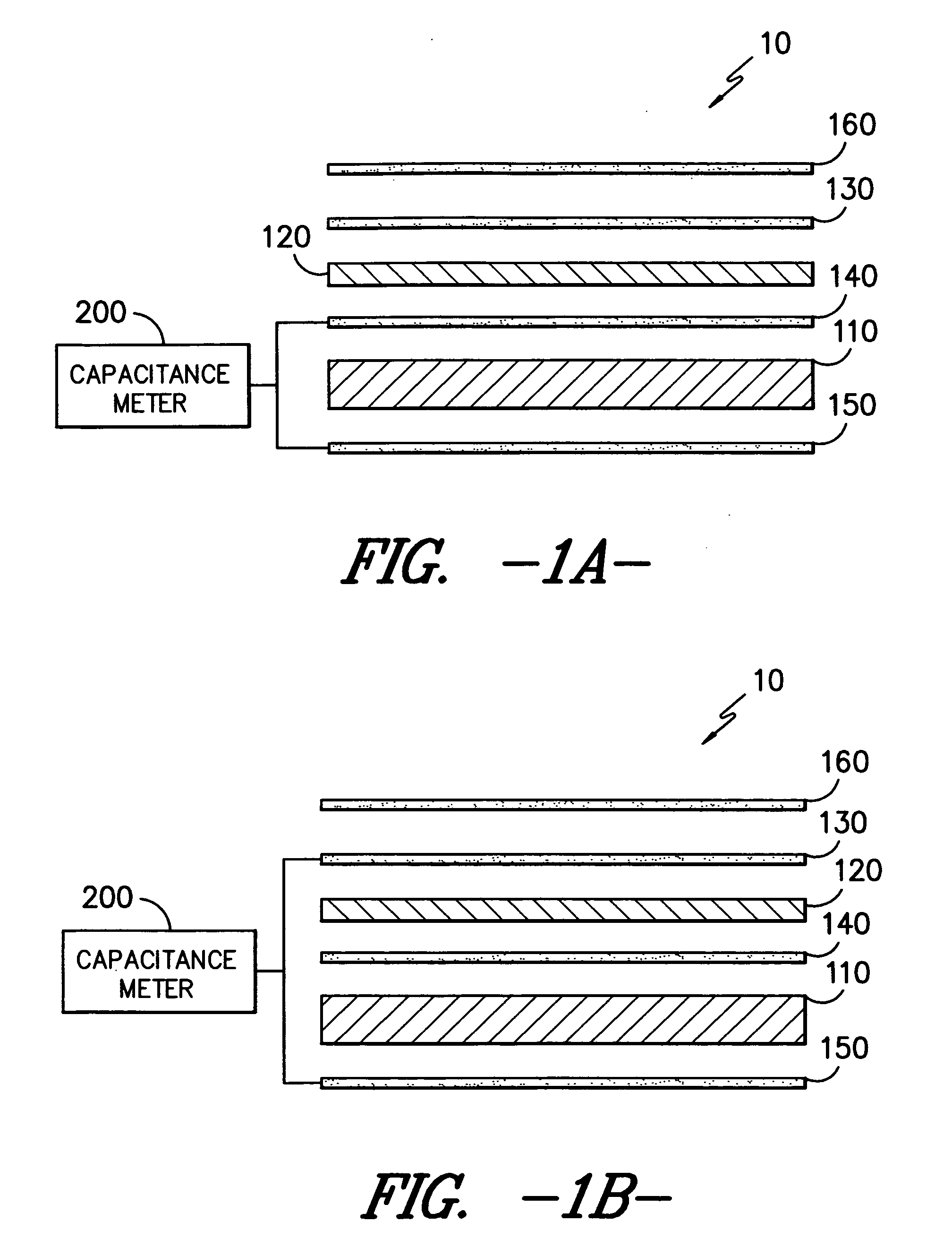
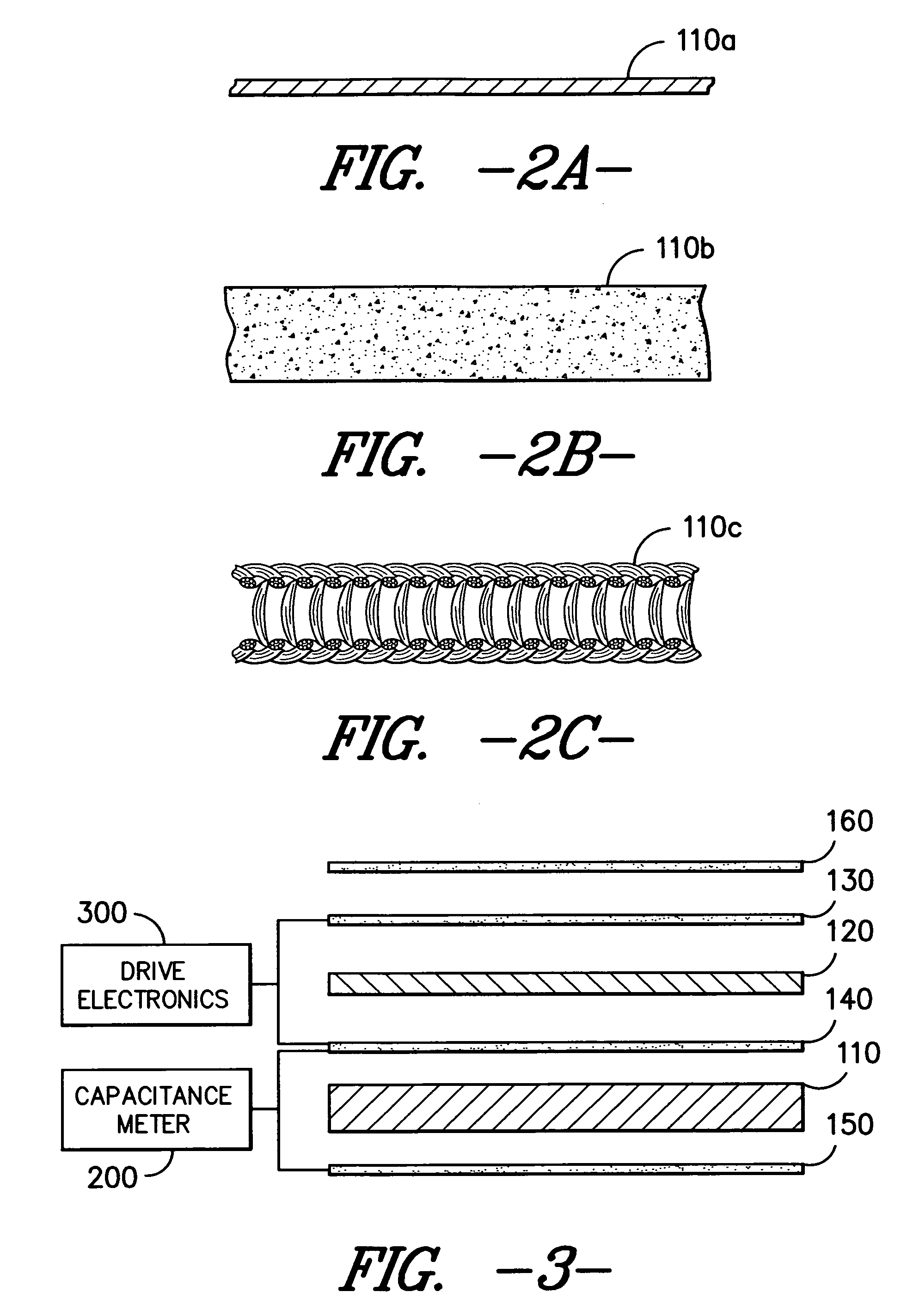
[0013]As depicted in FIGS. 1A and 1B, the flexible electroluminescent capacitive sensor 10 contains in order a first transparent barrier layer 160, a first transparent electrode layer 130, a phosphor layer 120, a second electrode layer 140, a flexible, resilient dielectric layer 110, and an electrically conductive reference layer 150. A capacitance meter 200 is connected to the second electrode layer 140 (in FIG. 1A) or the first electrode layer 130 (in FIG. 1B) and the electrically conductive reference layer 150. The capacitance meter 200 monitors the capacitive sensor 10 to determine whether there has been a change in capacitance and the extent of that change.
[0014]The flexible electroluminescent capacitive sensor 10 experiences a change in capacitance upon the application of force sufficient to compress the sensor. The amount of applied force, up to a point, is related to the extent of the change in capacitance. In an alternate embodiment, the resistance is also measured to deter...
PUM
 Abstract
Description
Claims
Application Information