Antenna apparatus

a technology of antenna and antenna surface, which is applied in the direction of antennas, antenna details, antenna earthings, etc., can solve the problems of difficult to secure the ground area necessary to obtain antenna characteristics, difficult to obtain the ground plane on the substrate, etc., and achieve the effect of sufficient antenna characteristics, high packaging density of parts, and sufficient antenna characteristics

Inactive Publication Date: 2009-11-05
MITSUBISHI MATERIALS CORP
View PDF5 Cites 12 Cited by
  • Summary
  • Abstract
  • Description
  • Claims
  • Application Information

AI Technical Summary

Benefits of technology

[0017]That is, according to the antenna apparatus according to the present invention, the RF ground conductor is branched to extend in at least two directions. As a result, a radiation efficiency similar to that of a ground with one large area is obtained, making it possible to have sufficient antenna characteristics. Therefore, even if a circuit ground conductor functioning as a digital circuit ground is brought into coexistence with an RF ground conductor on the same substrate, sufficient antenna characteristics are obtained. As a result, it is possible to achieve a high packaging density of parts and a downsizing of radio communication equipment.

Problems solved by technology

However, the prior art described above has problems as follows.
However, with a higher packaging density of parts, it has become difficult to secure a sufficient ground area necessary to obtain antenna characteristics in an ideal condition as shown in FIG. 5.
Furthermore, in the case where the RF ground conductor 3 and the circuit ground conductor 4 coexist on the same substrate 1 as shown in FIG. 6, there is a disadvantage that the ground plane on the substrate 1 is divided, making it impossible to secure the necessary area for the RF ground conductor 3.

Method used


Image

  • Antenna apparatus
  • Antenna apparatus
  • Antenna apparatus

Examples


examples

[0037]Next is a specific description of the results confirming the effect of the antenna apparatus according to the present invention by use of a simulation tool.

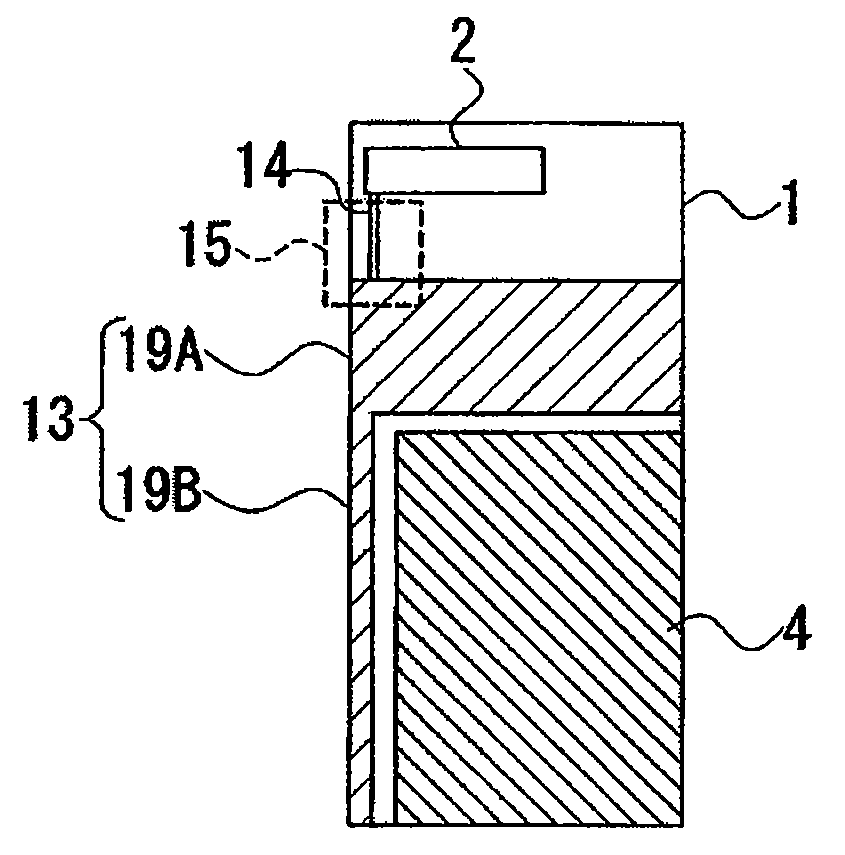
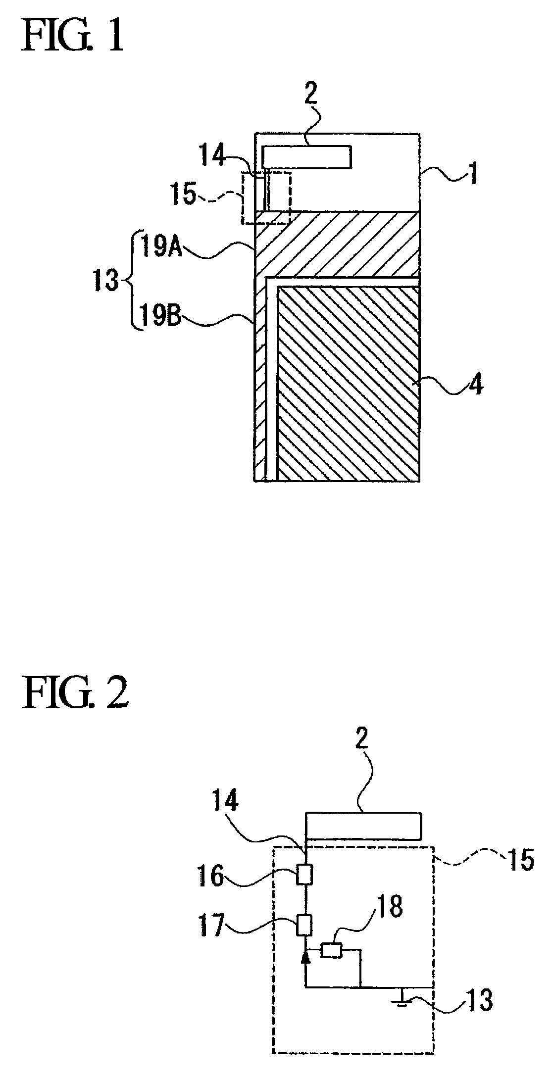
[0038]As calculation conditions for the simulation tool, the regulator circuit constants of the first inductor 16 to the third inductor 18 in the frequency regulation circuit 15 were respectively made A, B, and C. Furthermore, as constituent materials of the respective parts, an FR-4 with a specific inductive capacity of 4.9 was used in the substrate 1, and also an alumina base material with a specific inductive capacity of 9 was used in the chip antenna 2. The conductors in the conductor pattern and the surface of the substrate 1 were perfect conductors.

[0039]Table 1 below shows the results of the evaluation confirming the effect by the simulation tool performed on the above-mentioned embodiment (Invention 1) and another example of an embodiment (Invention 2) based on the above calculation conditions. Table 1 also shows th...


PUM


Abstract

An antenna apparatus includes: a substrate; an RF ground conductor which is branched to extend in at least two directions and at least a part of which is formed on a surface of the substrate, the RF ground conductor functioning as an antenna ground plane; and an antenna portion, one end of which is connected to the RF ground conductor.

Description

CROSS-REFERENCE TO PRIOR RELATED APPLICATIONS[0001]The present application is the U.S. National Stage of International Patent Application Serial No. PCT / JP2007 / 063142, filed on Jun. 29, 2007, which claims priority to Japanese Patent Application No. 2006-180513 filed Jun. 29, 2006, both of which are hereby incorporated by reference in their entirety.FIELD OF THE INVENTION[0002]The present invention relates to an antenna apparatus suitable for downsizing radio communication equipment.BACKGROUND[0003]In radio communication equipment such as mobile phones or note type personal computers with a built-in radio communication function, a packaging density of parts is increased as the radio communication equipment is reduced in size. To address this, an antenna apparatus as disclosed in, for example, Japanese Patent No. 3758495 is proposed. In this antenna apparatus, a spiral conductor layer is formed on the surface of a base material made of a dielectric material or a magnetic material. A s...

Claims


Application Information

Patent Timeline
Patent Type & Authority Applications(United States)
IPC IPC(8): H01Q1/48
CPCH01Q1/243H01Q1/362H01Q9/40H01Q1/48H01Q1/38H01Q1/24
Inventor LEE, SUNG-GYOONAKAMURA, MASAHIKOHIROSE, EIICHIROUYANAO, KOJI
Owner MITSUBISHI MATERIALS CORP
Why Eureka
Try Eureka