Simplified planetarium apparatus and simplified image projecting apparatus

a planetarium and simplified technology, applied in the field of simplified planetariums, can solve the problems of high production cost and assembly and adjustment cost of parts, difficult handling, and liable to be heavy on the apparatus body, and achieve the effect of limited projection range and low cos

Active Publication Date: 2009-11-05
OHIRA TAKAYUKI
View PDF5 Cites 13 Cited by
  • Summary
  • Abstract
  • Description
  • Claims
  • Application Information

AI Technical Summary

Benefits of technology

[0017]Preferably, the range to be projected is limited by providing a fixed aperture in front of or behind the transmissive base plate. Preferably, a sliding mechanism that changes the distance between the center axis of rotation of the transmissive base plate and the optical axis of the projection lens is provided. Preferably, the transmissive base plate is replaceable. Preferably, the light source is a light-emitting diode. Preferably, a complex effect of production is achieved by providing a plurality of the apparatus described above and electrical

Problems solved by technology

Therefore, there are problems such that the structure is complex, a large number of components are necessary, the part production cost and the assembly and adjustment cost are high, and the weight of the apparatus body is liable to be heavy, so that the handling is difficult.
Therefore, the usage is limited to places such as public facilities having sufficient financial resources.
However, since it has a configuration to project shadows, it is difficult to obtain sharp images.
In order to obtain the sharp images, it is necessary to use a light source having an extremely small light-emitting point, so that the choice of the light source is limited.
Furthermore, since the stellar projection sphere is composed of a polyhedron formed by assembling spherical materials or flat materials, punching holes on the spherical surface is costly, and when assembling flat projection base plates, there

Method used


Image

  • Simplified planetarium apparatus and simplified image projecting apparatus
  • Simplified planetarium apparatus and simplified image projecting apparatus
  • Simplified planetarium apparatus and simplified image projecting apparatus

Examples


Embodiment Construction

[0029]Referring now to the drawings, embodiments of the invention will be described in detail.

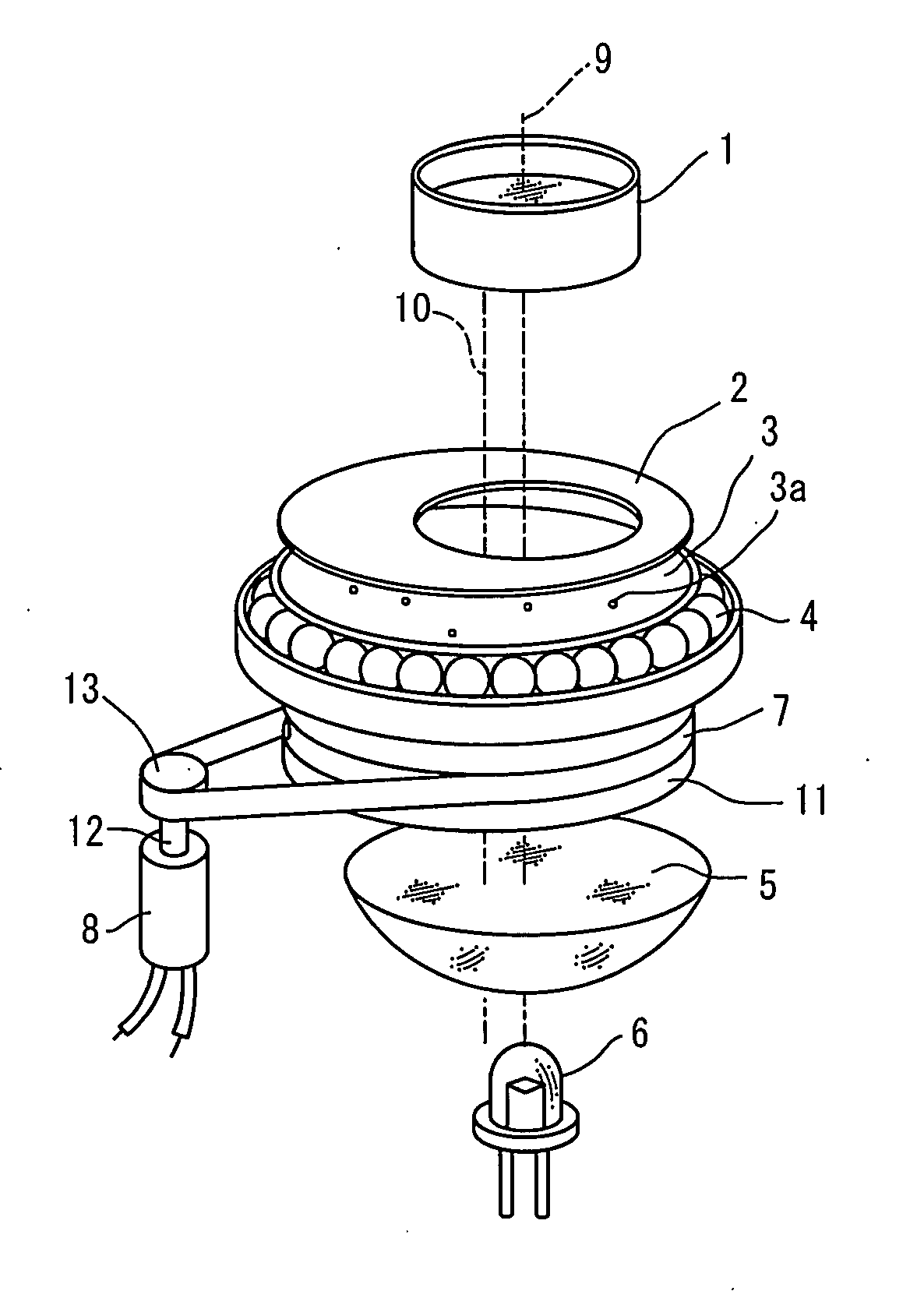
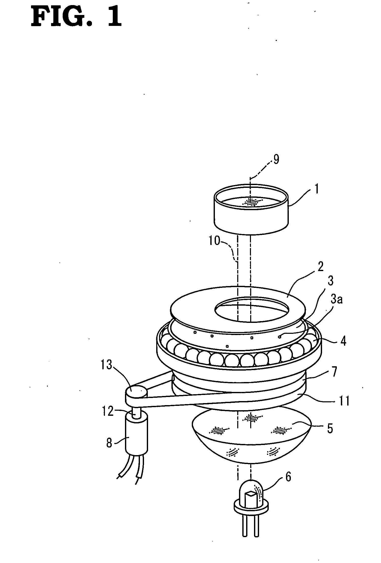
[0030]FIG. 1 is a schematic drawing showing an embodiment of a planetarium apparatus according to the invention. For example, light emitted from a light source 6 composed of, for example, a light-emitting diode passes through a condenser lens 5, then, passes through a stellar base plate 3, a fixed aperture 2, and a wide angled projection lens 1, and is projected on a screen, so that a starry sky is displayed thereon.

[0031]The stellar base plate 3 is a light-shielding metallic or plastic disk having a number of through holes 3a which correspond to the positions and brightness of actual stars, and is manufactured by etching on a metal thin film, or by application of a photographic film at low cost. When the photographic film is used, a transmissive pattern which corresponds to the through holes is exposed on the film. The stellar base plate 3 is supported by an inner ring of a ball bearing 4 ...


PUM


Abstract

Light emitted from a light source passes through a stellar base plate, a fixed aperture, and a wide-angled projection lens via a condenser lens and projects a starry sky on a screen. The stellar base plate is a light-shielding disk having a number of through holes which correspond to positions and brightness of actual stars, is supported by an inner ring of a ball bearing having the center at a position corresponding to the axis of rotation so as to be capable of rotating about the axis of rotation, and is driven by a motor via a belt. The centers of the projection lens, a window of the fixed aperture, the condenser lens, and the light source are all arranged on the optical axis, and the centers of the stellar base plate, the pulley and the ball bearing correspond to the axis of rotation.

Description

BACKGROUND OF THE INVENTION[0001]1. Field of the Invention[0002]The present invention relates to a simplified planetarium apparatus which is able to project a starry sky simply in a home environment, and an image projecting apparatus which is capable of projecting images.[0003]2. Description of the Related Art[0004]A planetarium apparatus which reproduces the starry sky and moves the starry sky as desired artificially even in the daytime achieves not only reproduction of the beautiful starry sky day and night for appreciation, but also reproduction of a celestial motion such as inerratic stars. Therefore, it is used all over the world as a preferable apparatus for leaning astronomy.[0005]FIG. 9 illustrates a basic configuration of a known optical planetarium apparatus. A stellar projection sphere 48 is supported so as to be capable of rotating about a diurnal axis 44, and the angle is set to an angle 46 which is the same as the latitude of an observation point. Reference numeral 43 ...

Claims


Application Information

Patent Timeline
IPC IPC(8): G03B21/14G09B27/00
CPCG03B21/14G09B27/06G03B37/04G03B21/142
Inventor OHIRA, TAKAYUKI
Owner OHIRA TAKAYUKI
Why Eureka
Try Eureka