System for providing on-die termination of a control signal bus

a control signal and on-die termination technology, applied in the field of computer memory, can solve the problems of occupying space on the memory module, increasing the cost of the memory module, and exacerbate the design challenges of the memory system

Active Publication Date: 2009-11-05
GLOBALFOUNDRIES US INC
View PDF8 Cites 56 Cited by
  • Summary
  • Abstract
  • Description
  • Claims
  • Application Information

AI Technical Summary

Benefits of technology

[0006]An exemplary embodiment includes a memory device that includes a plurality of data bus connectors, one or both of a load signal connector and a reset signal connector, a control bus connector, an ODT, and a mechanism. The ODT is in communication with the control bus connector, and the ODT provides a level of termination resistance to a control bus connected to the control bus connector. The mechanism latches data received via the data bus connectors in response to a signal received via one or both of the load signal connector and the reset signal connector. The data is utilized to set the level of termination resistance provided by the ODT.
[0007]Another exemplary embodiment includes a memory module including a control bus, a data bus, one or both of a load signal and a reset signal, and a memory device. The memory device includes a plurality of data bus connectors in communication with the data bus, one or both of a load signal connector in communication with...

Problems solved by technology

High-availability systems present further challenges as related to overall system reliability due to customer expectations that new computer systems will markedly surpass existing systems in regard to mean-time-between-failure (MTBF), in addition to offering additional functions, increased performance, increased storage, lower operating costs, etc.
Other frequent customer requirements further exacerbate the memory system design challenges, and include such items as ease of upgrade and reduced system envir...

Method used


Image

  • System for providing on-die termination of a control signal bus
  • System for providing on-die termination of a control signal bus
  • System for providing on-die termination of a control signal bus

Examples


Embodiment Construction

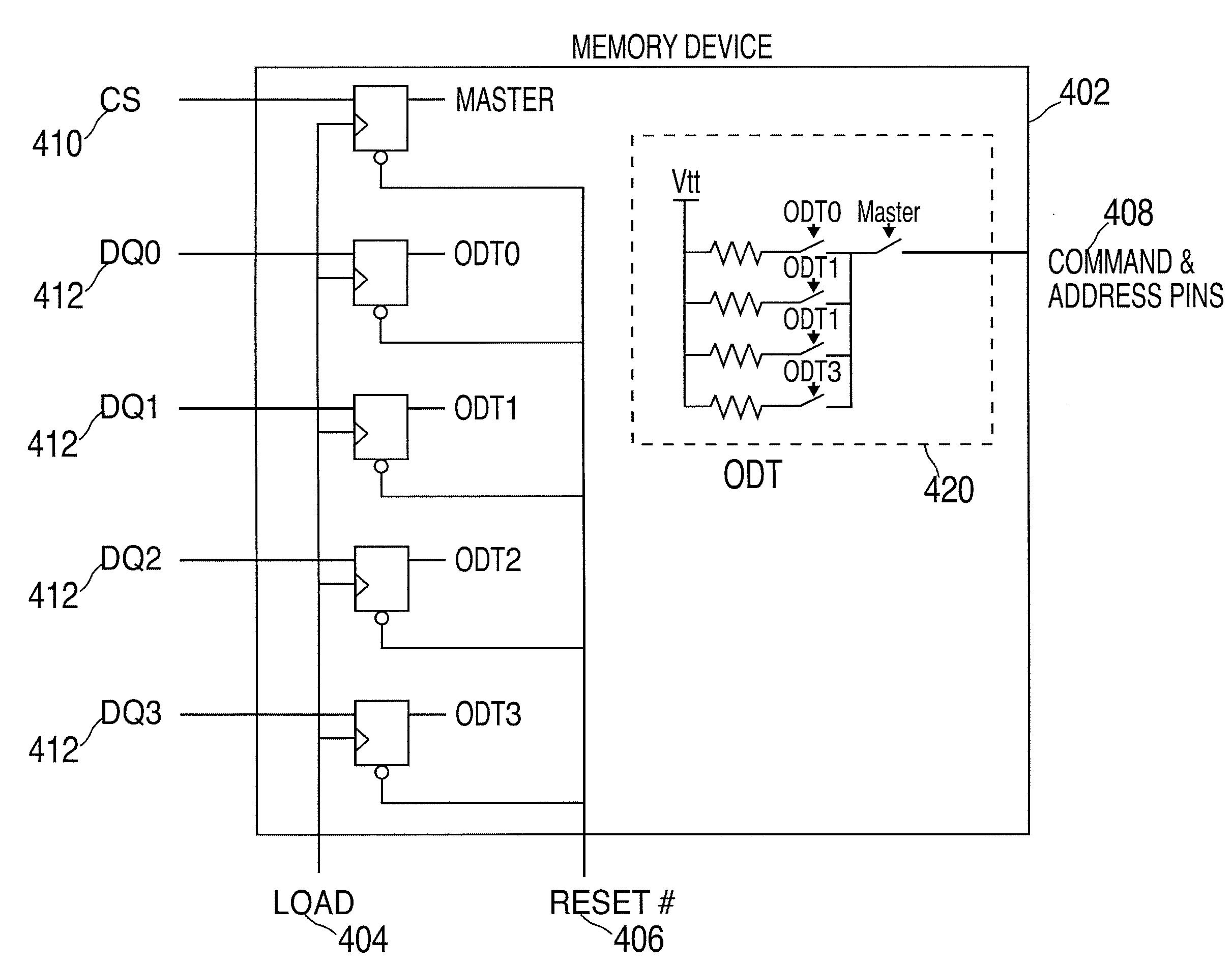
[0018]An exemplary embodiment of the present invention includes a system for providing on-die termination (ODT) of a control signal bus (e.g., an address and command bus). This includes the ability to have different memory devices on a memory module in different ODT states. For example, one memory device on a memory module could have the ODT turned on and the rest of the memory devices on the memory module could have the ODT turned off. In addition, the resistance setting of an ODT on one memory device on the memory module could be set to one value and the resistance setting of an ODT on a second memory device could be set to a second value. Exemplary embodiments provide flexibility in managing the states and resistance levels of a control signal bus in a memory subsystem.

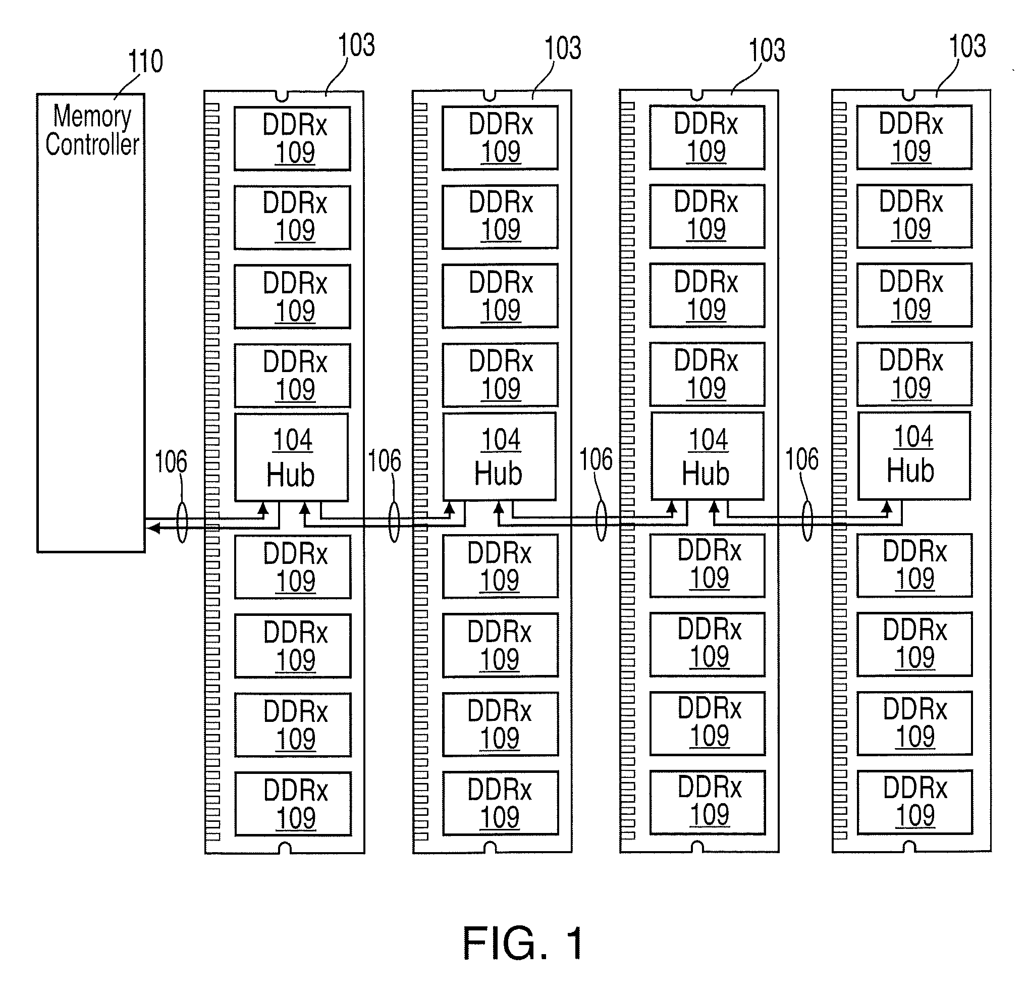
[0019]FIG. 1 depicts a memory system with cascaded memory modules 103 and unidirectional busses 106 that may be implemented by an exemplary embodiment. One of the functions provided by the hub devices 104 in the me...


PUM


Abstract

A system for providing on-die termination (ODT) of a control signal bus. The system includes a memory device that includes a plurality of data bus connectors, one or both of a load signal connector and a reset signal connector, a control bus connector, an ODT, and a mechanism. The ODT is in communication with the control bus connector, and the ODT provides a level of termination resistance to a control bus connected to the control bus connector. The mechanism latches data received via the data bus connectors in response to a signal received via one or both of the load signal connector and the reset signal connector. The data is utilized to set the level of termination resistance provided by the ODT.

Description

BACKGROUND OF THE INVENTION[0001]This invention relates generally to computer memory, and more particularly to providing on-die termination of a control signal bus.[0002]Contemporary high performance computing main memory systems are generally composed of one or more memory devices, which are connected to one or more processors via one or more memory control elements. These memory devices are generally located on a memory card module and connected through a module connector to a mother board.[0003]Overall computer system performance is affected by each of the key elements of the computer structure, including the performance / structure of the processor(s), any memory cache(s), the input / output (I / O) subsystem(s), the efficiency of the memory control function(s), the main memory devices(s), and the type and structure of the memory interconnect interface(s).[0004]Extensive research and development efforts are invested by the industry, on an ongoing basis, to create improved and / or innov...

Claims


Application Information

Patent Timeline
IPC IPC(8): G11C5/02G11C7/00H03K19/003
CPCG11C7/1048H04L25/0298G11C7/109G11C7/1078
Inventor KIM, KYU-HYOUNCOTEUS, PAUL W.
Owner GLOBALFOUNDRIES US INC
Why Eureka
Try Eureka