Apparatus and control interface therefor

a technology of control interface and apparatus, applied in the direction of electric digital data processing, pulse technique, instruments, etc., can solve the problems of increasing ic cost and complexity, increasing power consumption, and increasing ic area

Inactive Publication Date: 2009-11-05
NORTH STAR INNOVATIONS
View PDF16 Cites 42 Cited by
  • Summary
  • Abstract
  • Description
  • Claims
  • Application Information

AI Technical Summary

Benefits of technology

[0029]In summary, the preferred embodiment of the present invention proposes a mechanism for multiplexing multiple strobes on single control interface communication link (i.e. the same IC pin to accommodate different transceivers in a wireless communication device supporting multimode communication. The inventive concepts described herein propose to use the multiplexing of differing strobe signals to differentiate between intended state-machines or other functions internal to a sub-system such as the RFIC. In particular, different strobe signals are generated, multiplexed and decoded to trigger events on different sub-systems, based on, say a variable pulse code or variable pulse width or variable voltage magnitude associated with a strobe signal. This allows the strobe to be multiplexed to different state-machines that are internal to a radio sub-system, but still use the same interface connection.

Problems solved by technology

It is generally desirable to minimise the number of pins in ICs used in wireless communication devices, as the use of extra pins, for example on a BBIC-RFIC interface, increase IC area, increase IC cost and complexity and increase power consumption.
Multimode operational specs are not yet available.
So far, no solution has been proposed to convey layer 1 timing information to multiple transceivers using the same interface.
However, the technique proposed in US 200430071015 A1 would still not solve the aforementioned problem of wasting valuable resources, as it suggests latching a single strobe signal, per function.

Method used


Image

  • Apparatus and control interface therefor
  • Apparatus and control interface therefor
  • Apparatus and control interface therefor

Examples


first embodiment

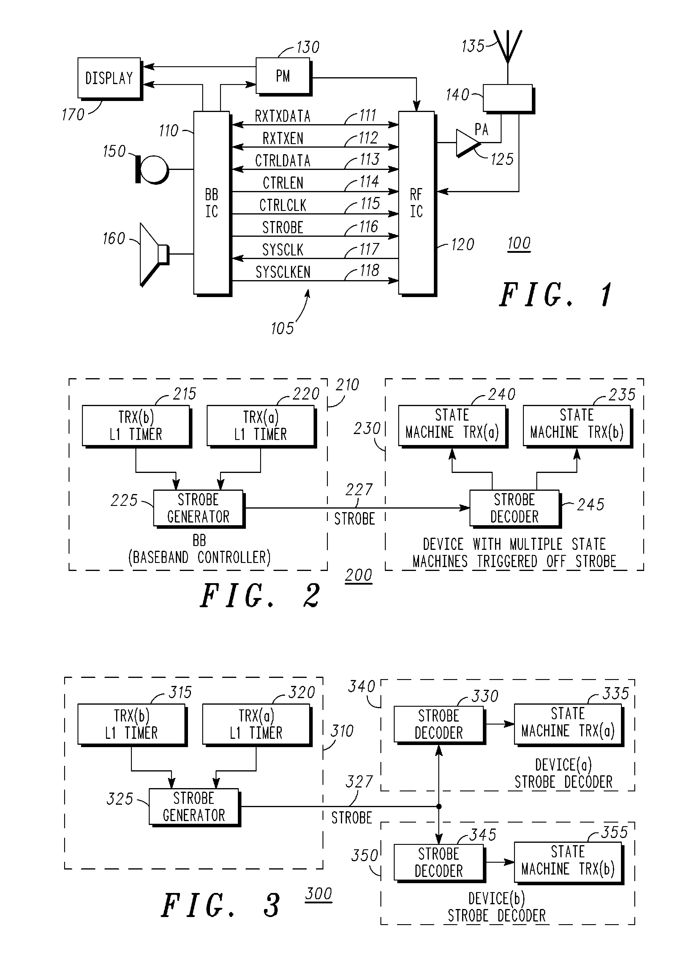
[0036]Referring next to FIG. 2, a strobe generation and decoding system 200 is illustrated, in accordance with the present invention. Notably, the strobe generation and decoding system illustrates a scenario when one device is used with multiple internal state machines. A state machine is any device that stores the status of something at a given time and can operate on input to change the status and / or cause an action or output to take place for any given change. The main function of the state machine on the RFIC is the control and timing of calibration, RX and TX events.

[0037]A baseband controller 210 comprises the strobe generation and decoding system 200, for example a baseband controller of a BBIC, comprises two Layer-1 timers 215 and 220, operably coupled to a strobe generator 225 that generates a strobe signal 227. A Layer 1 timer function in a baseband processor is used in mobile communication terminals. It is used to correctly time events on the air interface of the respecti...

second embodiment

[0042]Referring next to FIG. 3, a strobe generation and decoding system 300 is illustrated, when multiple devices 340, 350 are connected to the baseband controller 310, in accordance with the present invention. Each of the multiple corresponding receiving devices (or elements or ICs, such as an RFIC) preferably comprise a strobe decoder system 330, 345 and one or more state machines 335, 355 internal to the devices 340350.

[0043]In this embodiment, one or both Layer-1 timers 315, 320 on the baseband controller 310 are again able to trigger the strobe generator 325. The strobe generator 325 generates a specific multiplexed strobe signal 327 (based on a number of variable strobe codes and / or strobe amplitudes). Again, the strobe generator 325 forwards the multiplexed strobe signal 327 across the control interface to one or more of the devices 340, 350. The multiplexed strobe signal 327 is decoded and de-multiplexed into multiple differing strobe signals, such that each device 340, 350 ...

third embodiment

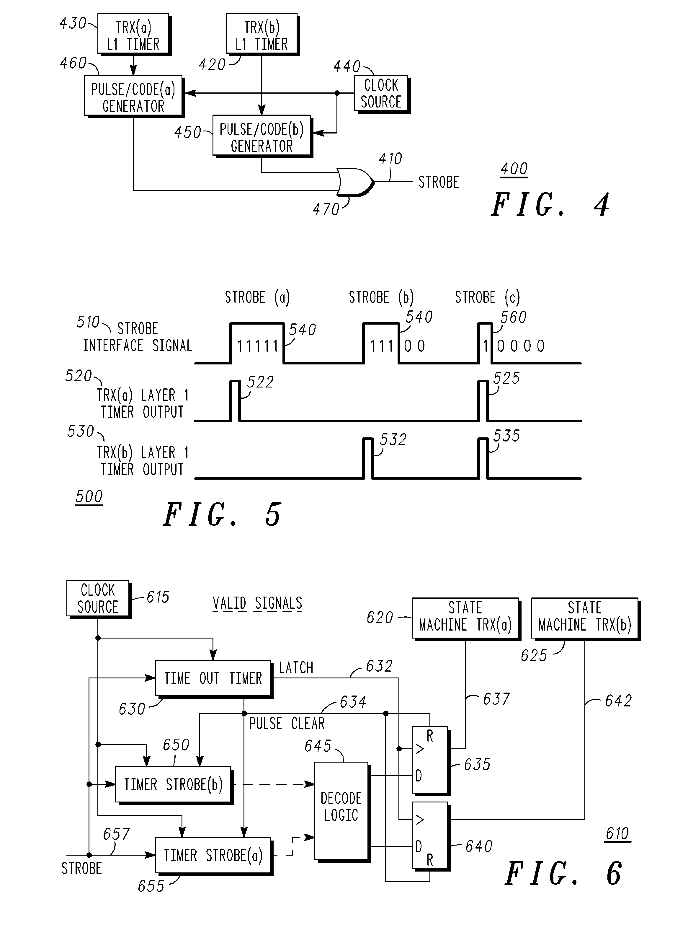
[0048]Referring next to FIG. 5, a timing diagram 500 illustrates strobe generator waveforms (inputs 520, 530 and resultant outputs 510), in accordance with FIG. 4. As illustrated on a first Layer-1 waveform, a first Layer-1 timer triggers 522 the pulse code generator. The pulse code generator generates a Strobe interface output signal 510 comprising a specific code 540 that indicates that the Layer-1 timer 522 has triggered the generation of the Strobe interface signal. Similarly, a second Layer-1 timer output 532 may also trigger the (respective) pulse code generator. The pulse code generator generates a Strobe interface output signal 510 comprising a specific code 540 that again indicates that the second Layer-1 timer 535 has triggered the generation of the Strobe interface signal. Thus, preferably each Layer-1 timer generates a separate strobe code. If both Layer-1 timers generate simultaneously a trigger pulse 525, 535, then it is envisaged that both of the outputs of the pulse ...


PUM


Abstract

An apparatus comprises a number of sub-systems and a control interface operably coupled to sub-systems for routeing data therebetween. A strobe generation function is operably coupled to the control interface and configured to generate a plurality of different strobe signals to differentiate between different intended receiving devices. Thus, different strobe signals may be multiplexed onto a single control interface link, based on a pulse width or voltage magnitude characteristics of the respective strobe signals. A strobe decoder function is operably coupled to the control interface and configured to decode a plurality of different strobe signals to differentiate between triggering sub-systems on receiving devices.

Description

FIELD OF THE INVENTION[0001]This invention relates to an apparatus and a control interface therefor. The invention is applicable to, but not limited to, control interfaces for wireless communication devices, particularly multimode wireless communication devices.BACKGROUND OF THE INVENTION[0002]Wireless communication devices, such as mobile phone handsets, require a very high level of integration of hardware and firmware / software in order to achieve the necessary density of functionality, i.e. to realise the necessary functionality in a minimum device volume and at a minimum cost. An optimal wireless communication device design must also minimise power consumption in order to increase the battery call time and / or stand-by time.[0003]Wireless communication devices also incorporate a number of distinct and operably coupled sub-systems, in order to provide the wide variety of functions and operations that a complex wireless communication device needs to perform. Such sub-systems compris...

Claims


Application Information

Patent Timeline
Patent Type & Authority Applications(United States)
IPC IPC(8): H03K7/08H04W88/02
CPCG06F13/4291
Inventor O'KEEFFE, CONORKELLEHER, PAULSCHWARTZ, DANIEL
Owner NORTH STAR INNOVATIONS
Why Eureka
Try Eureka