Optical add-drop apparatus and method

a technology of add-drop apparatus and optical filter, which is applied in the field of optical add-drop apparatus, can solve the problems of high reliability and high cost performance, the inability to extend the channel number of the channel selector beyond the predetermined prepared number, and the drop multiplexer, so as to reduce the number of expensive filters and reduce the number of filters

Inactive Publication Date: 2005-01-20
NEC CORP
View PDF11 Cites 29 Cited by
  • Summary
  • Abstract
  • Description
  • Claims
  • Application Information

AI Technical Summary

Benefits of technology

[0018] In this invention, the demultiplex main wavelength filtering portion may comprise a first demultiplex wavelength filter for separating the input signal into the passing signal and the intermediate output signal, the demultiplex sub wavelength filtering portion may comprise a second demultiplex filter for separating the intermediate output signal into the dropped signal and the extended output signal, and the second demultiplexing unit may comprise an interleaver. In this event, if three wavelength filters and three inter...

Problems solved by technology

However, the first conventional optical add-drop multiplexer is disadvantageous in that it is impossible to extend the channel number of the channel selector beyond the predetermined prepared number or more.
According to Ohaka, the optical wavelength multiplex network uses an acoustooptic...

Method used


Image

  • Optical add-drop apparatus and method
  • Optical add-drop apparatus and method
  • Optical add-drop apparatus and method

Examples


first embodiment

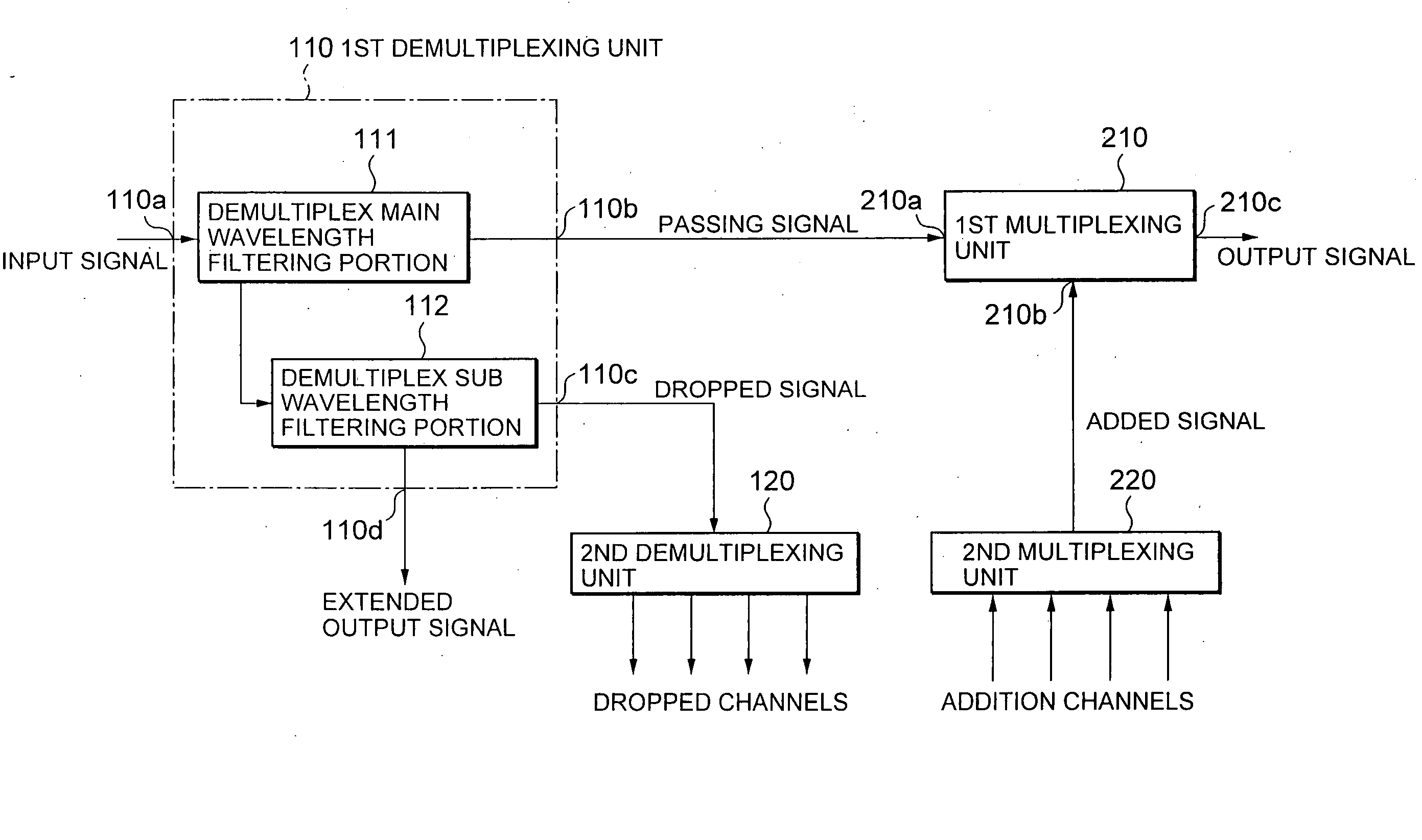
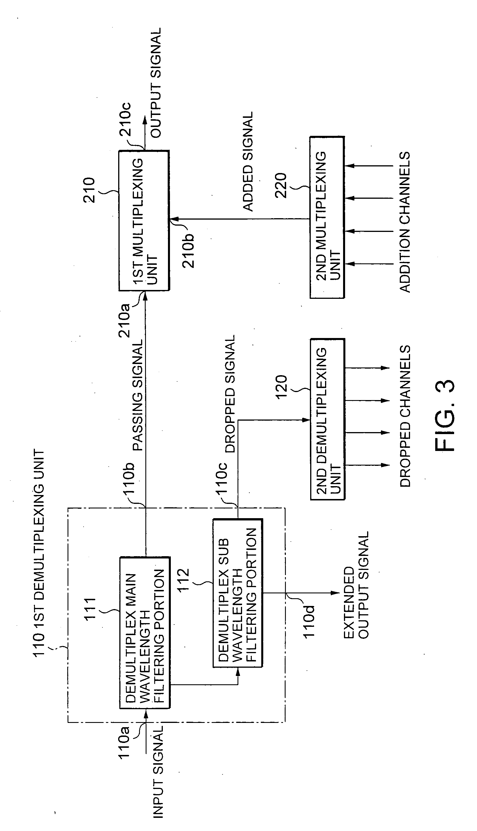
[0048] Referring to FIG. 3, the description will proceed to an optical add-drop apparatus according to this invention. The illustrated optical add-drop apparatus picks up, a dropped signal, a signal having a particular wavelength from an input signal transmitted in a wavelength-multiplexed fashion and adds an add signal to a passing signal to produce an output signal.

[0049] The optical add-drop apparatus comprises a first demultiplexing unit 110, a second demultiplexing unit 120, a first multiplexing unit 210, and a second multiplexing unit 220.

[0050] The first demutiplexing unit 110 has an input port 110a for inputting the input signal, a through output port 110b for outputting the passing signal, a dropping port 110c for outputting the dropped signal, and an extended output port 110d for outputting the extended output signal.

[0051] The first demultiplexing unit 110 comprises a demultiplex main wavelength filtering portion 111 for separating the input signal into the through sign...

second embodiment

[0066] Referring to FIG. 6, the description will proceed to an optical add-drop apparatus according to this invention. The illustrated optical add-drop apparatus is similar in structure and operation to the optical add-drop apparatus illustrated in FIG. 3 except that the first multiplexing unit further has an extended input port 210d for inputting an extended input signal. The first multiplexing unit is therefore depicted at 210A.

[0067] The first multiplexing unit 210A comprises a multiplex main wavelength filtering portion 211 and a multiplex sub wavelength filtering portion 212. The multiplex sub wavelength filtering portion 212 multiplexes the added signal and the extended input signal to produce an intermediate input signal. The multiplex main wavelength filtering portion 211 multiplexes the passing signal and the intermediate input signal to produce the output signal. The multiplex main wavelength filtering portion 211 comprises, for example, a third wavelength variable filter ...

third embodiment

[0120] Referring to FIG. 19, the description will proceed to an optical add-drop apparatus according to this invention. The illustrated optical add-drop apparatus is similar in structure and operation to the optical add-drop apparatus illustrated in FIG. 7 except that the first demultiplexing unit and the first multiplexing unit are modified from those illustrated in FIG. 7 as will later become clear and the wavelength setting portion is modified from that illustrated in FIG. 7. The first demultiplexing unit, the first multiplexing unit, and the wavelength setting portion are therefore depicted at 110A, 210A, and 200. The similar reference symbols are attached to those having similar functions in illustrated in FIG. 7.

[0121] The illustrated optical add-drop apparatus shows an example devised so as to make a plurality of wavelength bands the passing signal.

[0122] The first demultiplexing unit 110A has first and second through output ports 110b and 110b2 for outputting first and seco...


PUM


Abstract

A wavelength variable filter (111) separates an input signal into a passing signal and an intermediate output signal. A wavelength variable filter (112) separates the intermediate output signal into a dropped signal and an extended output signal. An interleaver (120) separates the dropped signal into individual dropped channels. An intrerleaver (220A) multiplexes a plurality of addition channels into an added signal. A wavelength variable filter (212) multiplexes the added signal and an extended input signal to produce an intermediate input signal. A wavelength variable filter (211) multiplexes the passing signal and the intermediate input signal into an output signal. A wavelength setting portion (100) sets a wavelength of each wavelength variable filter in accordance with operation of an operator.

Description

[0001] This application claims priority to prior Japanese patent application JP 2003-160950, the disclosure of which is incorporated herein by reference. BACKGROUND OF THE INVENTION [0002] This invention relates to an optical add-drop apparatus for use in an optical wavelength multiplex transmission system. [0003] The optical add-drop apparatus is an apparatus for picking up a light signal having a particular wavelength from a wavelength-multiplexed signal (an input signal) and for adding a light signal having the particular wavelength to a through signal to produce an output signal. [0004] Such an optical add-drop apparatus is disclosed, for example, in U.S. Pat. No. 6,452,703 issued to Sung-jun Kim et al. According to Kim, a first conventional optical add-drop apparatus comprises a wavelength group demultiplexer (DMUX), a wavelength group multiplexer (MUX), a channel selector, and a channel multiplexer, in the manner which will later be described in conjunction with FIG. 1. The wa...

Claims


Application Information

Patent Timeline
IPC IPC(8): H04B10/27H04B10/29H04B10/291H04J14/00H04J14/02
CPCH04J14/0208H04J14/0219H04J14/021
Inventor MATSUDA, OSAMU
Owner NEC CORP
Why Eureka
Try Eureka