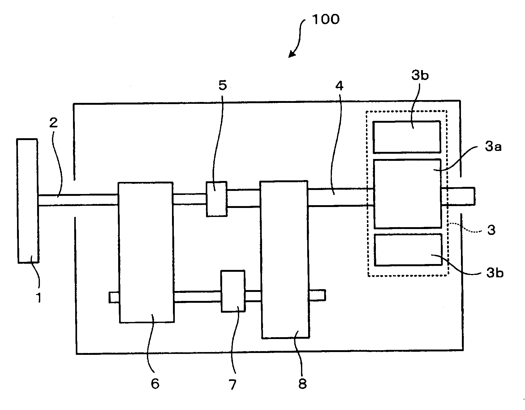
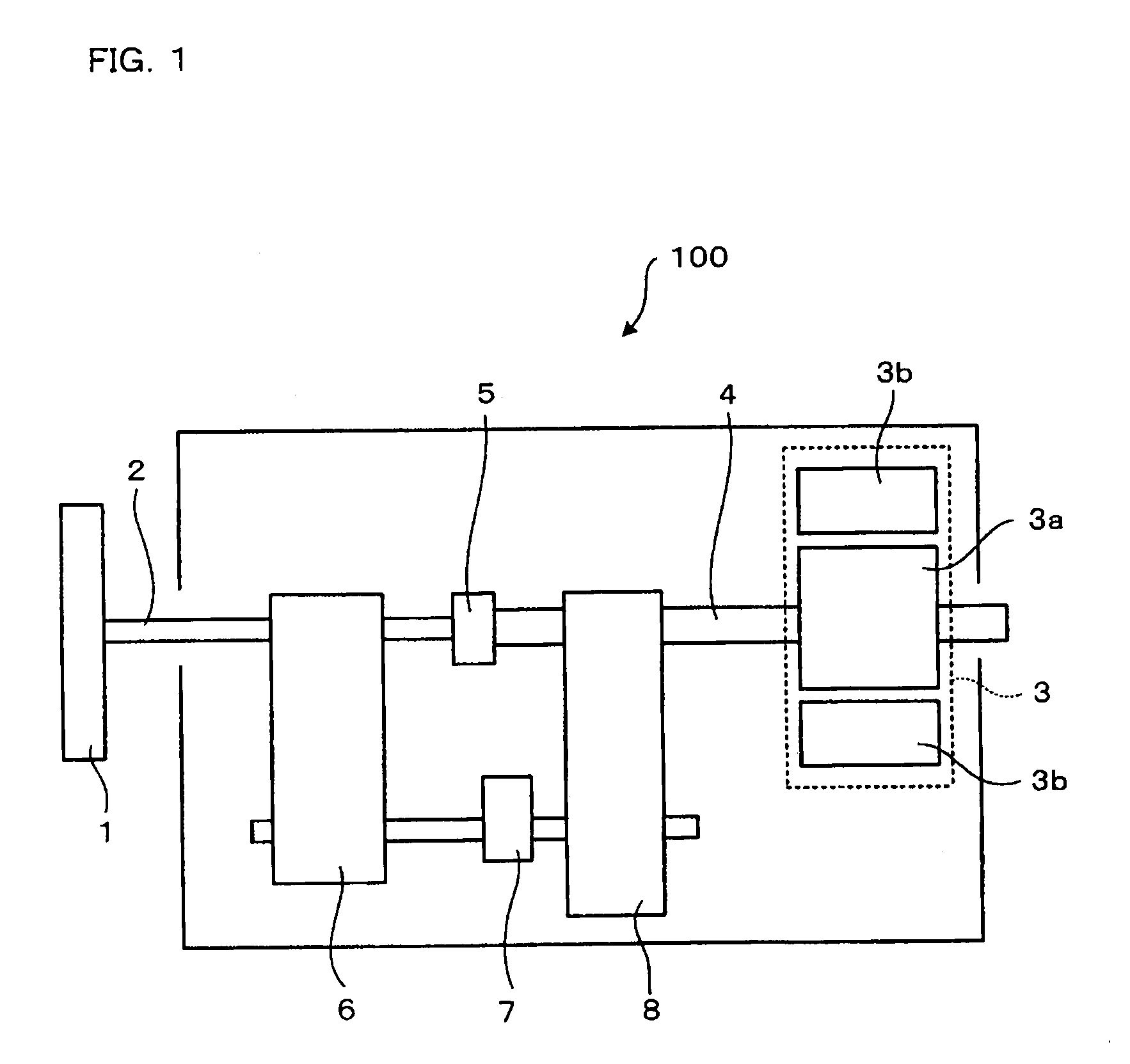
[0006]A power generating device of the present invention includes: a first rotary shaft rotated by an external rotational force; a second rotary shaft rotated by the rotation from the first rotary shaft; a power generator rotated by the rotation from the second rotary shaft, which generates a power; first transmitting means for transmitting the rotation of the first rotary shaft as it is to the second rotary shaft; second transmitting means for increasing the rotation frequency of the rotation received from the first rotary shaft, and transmitting the rotation with the increased rotation frequency to the second rotary shaft. The first transmitting means includes first connecting means for (i) disconnecting the first and second rotary shafts from each other when a rotation frequency of the first rotary shaft is not more than a predetermined value, and (ii) connecting the first and second rotary shafts with each other when the rotation frequency of the first rotary shaft surpasses the predetermined value. The second transmitting means includes: (A) an acceleration gearing
system having a plurality of gears, which increases the rotation frequency of the rotation received from the first rotary shaft, and transmits the rotation with the increased rotation frequency to the second rotary shaft, and (B) second connecting means for (i) connecting the first and second rotary shafts with each other via the acceleration gearing system when the rotation frequency of the first rotary shaft is not more than the predetermined value, and (ii) disconnecting the first and second rotary shafts connected via the gearing system from each other when the rotation frequency of the rotary shaft surpasses the predetermined value.
[0007]With this, the first connecting means disconnects the first and second rotary shafts from each other when a rotation frequency of the first rotary shaft is not more than a predetermined value, and connects the first and second rotary shafts with each other when the rotation frequency of the first rotary shaft surpasses the predetermined value. Accordingly, even when the rotation frequency of the first rotary shaft is low, the rotation frequency of the power generator rotating with the second rotary shaft is kept from dropping too low a frequency, and power generation is surely performed. On the other hand, when the rotation frequency of the first rotary shaft surpasses the predetermined value, the first connecting means connects the first and second rotary shafts with each other, and the second connecting means disconnects the first and second rotary shafts which are connected with each other via the acceleration gearing system. Thus, the rotation of the first rotary shaft is transmitted as it is to the second rotary shaft. Accordingly, even when the rotation frequency of the first rotary shaft is high, it is possible to avoid occurrence of a large centrifugal force, and damaging the power generator rotating with the second rotary shaft by the centrifugal force. Further, it is not necessary to upsize the power generator so as to make it resistant against a large centrifugal force. Therefore, the downsizing of the entire device is possible. Further, since the acceleration gearing system of the second transmitting means includes a plurality of gears, the structure of the device is simplified, and the maintenance of the device will be easy.
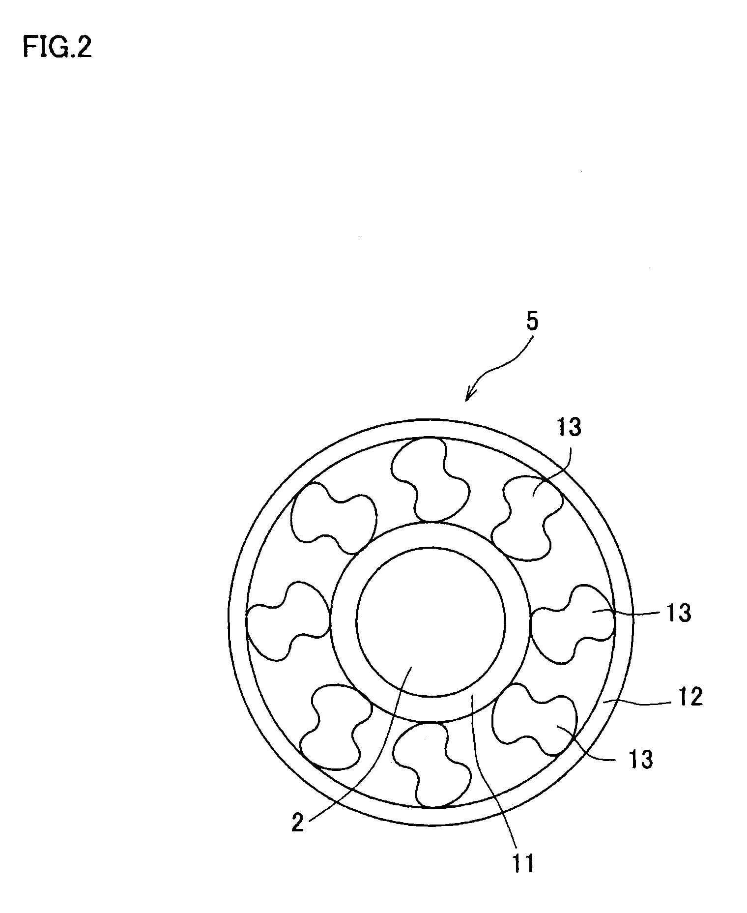
[0008]Further, the power generating device of the present invention may be adapted so that the first connecting means is a freewheel clutch including: a first rotating member which rotates with the first rotary shaft; a second rotating member which rotates with the second rotary shaft; and a connecting member which (i) connects the first and second rotating members with each other when the rotation frequency of the first rotating member is not lower than the rotation frequency of the second rotating member, and (ii) disconnects the first and second rotating members from each other when the rotation frequency of the first rotating member is lower than the rotation frequency of the second rotating member. In this structure, the first connecting means is a freewheel clutch. Therefore, when the rotation frequency of the first rotary shaft is not more than a predetermined value, the second connecting means connects the first and the second rotary shafts via the acceleration gearing system, and the rotation frequency of the rotation from the first rotary shaft is increased and is transmitted to the second rotary shaft. Therefore, the rotation frequency of the first rotary shaft is lower than that of the second rotary shaft, and the first and the second rotating members connected via connecting members are disconnected from each other. On the other hand, when the rotation frequency of the first rotary shaft surpasses the predetermined value, the second connecting means disconnects the first and second rotary shafts which are connected to each other via the acceleration gearing system. Therefore the rotation frequency of the second rotary shaft drops, and when the rotation frequency reaches the rotation frequency of the first rotary shaft, the first and the second rotating members are connected via the connecting members. Accordingly, it is possible to realize the entire device with a simple structure in which the first and the second rotary shafts are connected / disconnected to / from each other by means of the freewheel clutch.
[0009]Further, the power generating device of the present invention may be adapted so that the first and second rotary shafts are disposed along a single straight line; and the acceleration gearing system of the second transmitting means and the second connecting means are disposed so that their respective barycenters are positioned along the straight line. This structure restrains vibration occurring while the rotation of the first rotary shaft is transmitted to the second rotary shaft.
[0010]Further, a power generating device of the present invention includes: a first rotating member which rotates with an external rotational force; a second rotating member rotated, in a direction opposite to the first rotating member, by the external rotational force; a power generator including (i) a rotor which rotates with the first rotating member, and (ii) a
stator disposed so as to surround the rotor, which rotates with the second rotating member, in a direction opposite to the rotor; and a stopping member which stops the rotation of the second rotating member, wherein the stopping member stops the rotation of the second rotating member when the rotation frequency of the first rotating member surpasses a predetermined value.
[0011]With this, when the rotation frequency of the first rotating member is not more than a predetermined value, the first rotating member rotates and the second rotating member rotates in a direction opposite to the first rotating member. Therefore, the rotor rotates relative to the
stator, at a rotation frequency which is the sum of the rotation frequencies of the rotor and the
stator, and therefore enables power generation even when the rotation frequency of the first rotating member is low. On the other hand, when the rotation frequency of the first rotating member surpasses a predetermined value, the first rotating member rotates and thereby rotates the rotor, while the stopping mechanism stops the rotation of the second rotating member. The rotor therefore rotates relative to the stator at the rotation frequency of its own, thereby generating power. As described, the rotation frequency of the rotor relative to the stator is increased by rotating the stator and the rotor in the opposite directions to each other, instead of, for example, transmitting the rotation from the first rotating member to the rotor, while increasing the rotation frequency of the rotation through the process of transmitting the rotation. Thus, when the rotation frequency of the first rotating member is increased, the rotation frequency of the rotor on the other hand is not increased by much. Therefore, a large centrifugal force does not occur in the power generator. Thus, it is not necessary to upsize the power generator to make it resistant against a large centrifugal force. Further, it is possible to realize the device with a simple structure.

