Drag reducing devices for stacked intermodal rail cars

a technology of drag reducing device and intermodal rail car, which is applied in the direction of air resistance reduction technology, roofs, transportation and packaging, etc., can solve the problems of significant increase in the cost of operating a diesel powered locomotive, damage, and environmental damage,

Inactive Publication Date: 2009-11-12
UNION PACIFIC RAILROAD
View PDF36 Cites 10 Cited by
  • Summary
  • Abstract
  • Description
  • Claims
  • Application Information

AI Technical Summary

Benefits of technology

[0006]Another aspect of the invention includes a method for reducing aerodynamic drag of a series of stacked intermodal containers. The series has at least a first, leading set of containers with a top container stacked above a bottom container. Each of the containers has a top wall, a bottom wall, front wall, back wall, and side walls connected by a frame. The bottom wall has a tunnel extending from a first end of the container toward a second end of the container. The method of reducing drag includes providing an aerodynamic drag reducing device having a drag reducing fairing attached to an attachment frame and removably mounting the attachment frame using at least one mounting device extending rearwardly from the attachment frame in the tunnel of the top container of the first, leading set of containers.

Problems solved by technology

For example, the expenses associated with operating a fuel (e.g., diesel) powered locomotive may significantly increase based on rising gas prices.
Additionally, exhaust emissions of diesel fuel may cause damage and be harmful to the environment.

Method used


Image

  • Drag reducing devices for stacked intermodal rail cars
  • Drag reducing devices for stacked intermodal rail cars
  • Drag reducing devices for stacked intermodal rail cars

Examples


Embodiment Construction

)

[0024]It is a goal of the present invention to reduce the amount of aerodynamic drag and vortices created among a series of stacked intermodal containers during transportation. Though intermodal containers are designed to be used in more than one form of transportation, e.g., railway, waterway, or highway, the embodiments below are herein described pertaining to their use on a railway.

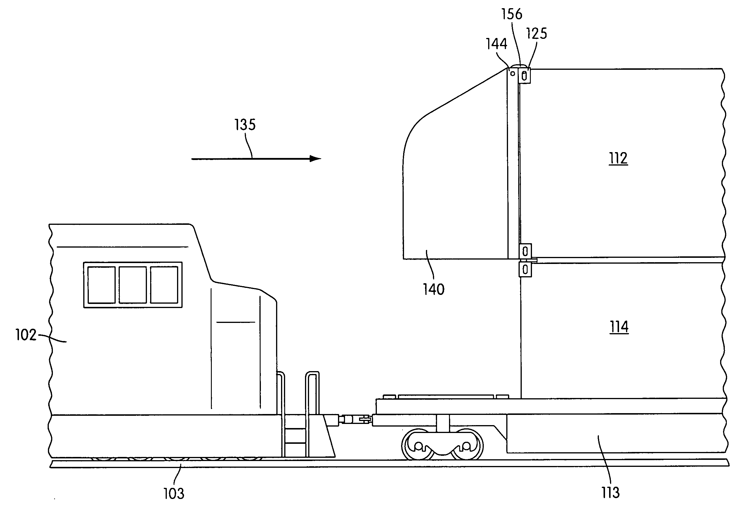
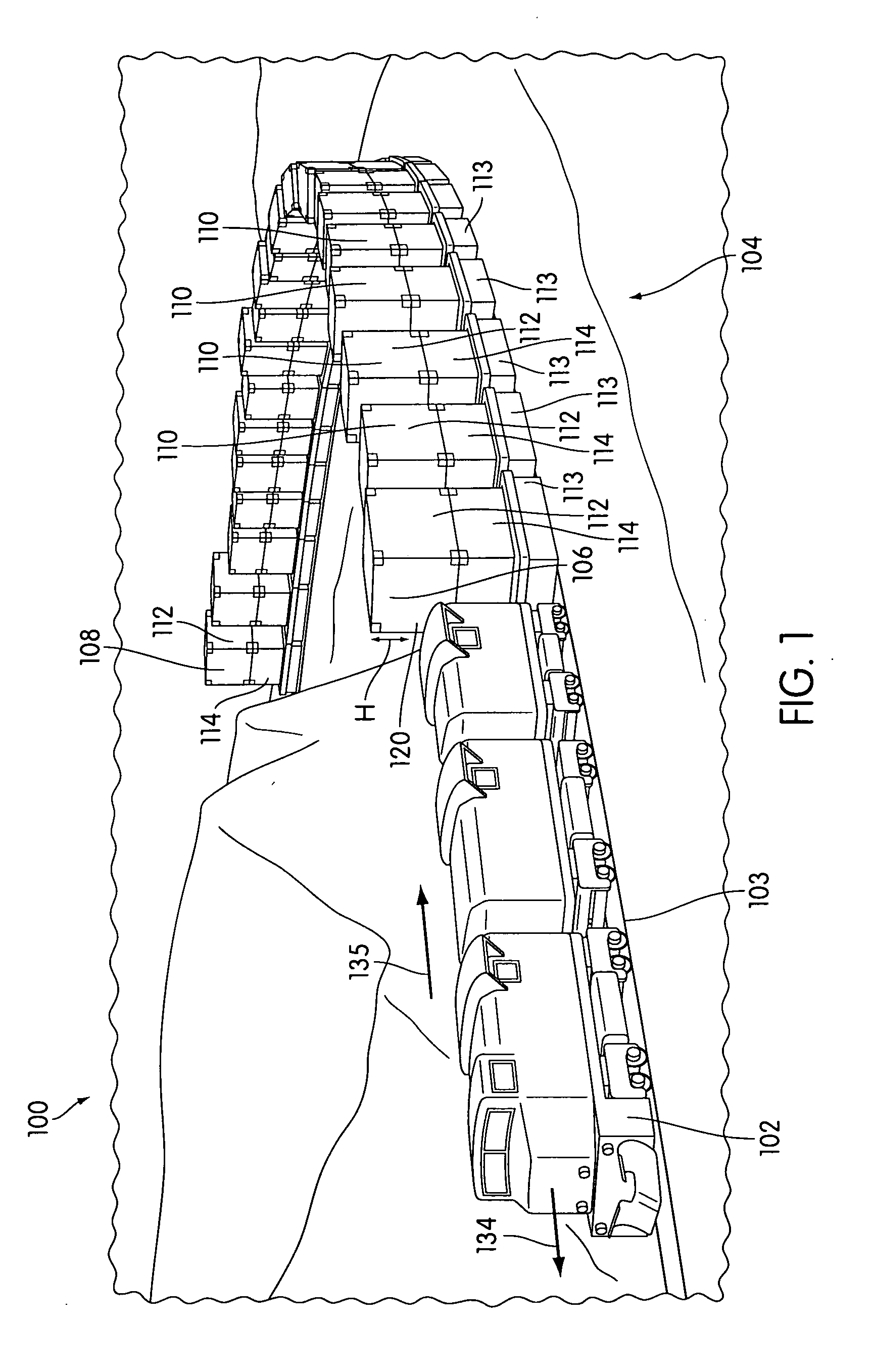
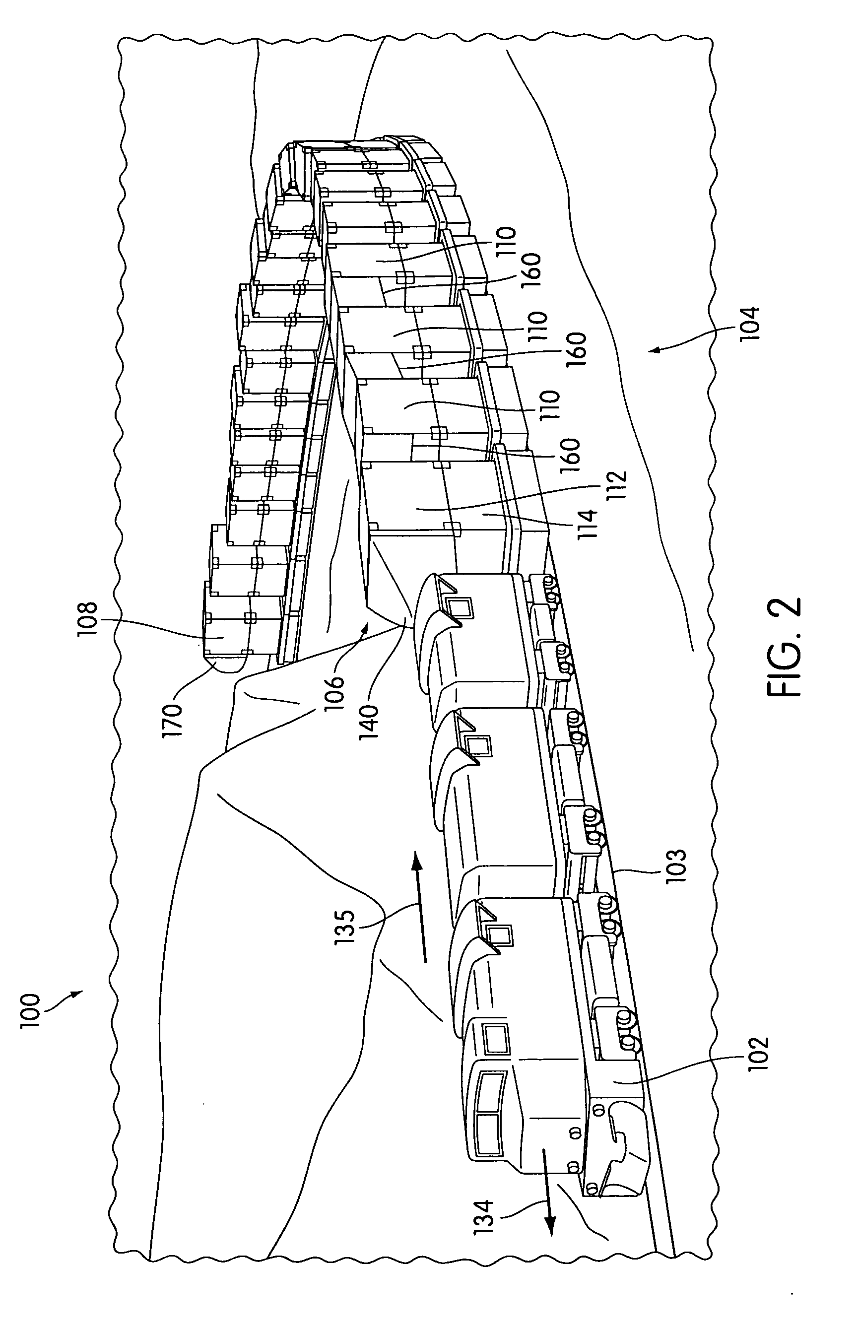
[0025]Referring now more particularly to the drawings, FIG. 1 illustrates a train 100 comprising a locomotive 102 pulling a series104 of stacked intermodal containers, as previously noted. The locomotive 102 may be a vehicle that is diesel-powered to pull the series 104 of stacked intermodal containers on railroad tracks or rails 103, as is known in the art. As shown, the series 104 has at least a first, leading set 106 of stacked intermodal containers, and at least a second, trailing set of stacked intermodal containers 108. The first, leading set 106 of containers is defined as a first set of contai...


PUM


Abstract

Disclosed is a series of stacked intermodal containers, being pulled by a locomotive of a train, with aerodynamic drag reducing devices. The series includes at least a first, leading set of containers and a second, trailing set of containers. The first, leading set of containers has an aerodynamic drag reducing device with a drag reducing fairing and an attachment frame attached thereto facing a forward direction. The attachment frame includes at least one mounting device configured to be removably mounted in the tunnel of the top container of the first, leading set of containers. Additionally, the second, trailing set of containers may include a second, aerodynamic drag reducing device. Curtains may also be attached between a plurality of intermediate or adjacent sets of stacked containers to assist in reducing drag on the train when moving.

Description

BACKGROUND[0001]1. Field of Invention[0002]The present invention is generally related to reducing aerodynamic drag on stacked intermodal containers.[0003]2. Description of Related Art[0004]Generally the use of stacked (or “double stacked”) intermodal containers, wherein a top container is mounted on a bottom container, is known as a method of transporting goods on rail. For example, as shown in FIG. 1 and further described in detail below, a series 104 of stacked intermodal containers may be provided on stack cars 112 and pulled by a locomotive 102 along a rail 103 to form a train used for transporting goods on land. Though transporting intermodal containers in a double stack assists in lowering rail haul costs, it would be beneficial to further reduce such costs associated with rail transportation. For example, the expenses associated with operating a fuel (e.g., diesel) powered locomotive may significantly increase based on rising gas prices. Additionally, exhaust emissions of die...

Claims


Application Information

Patent Timeline
Patent Type & Authority Applications(United States)
IPC IPC(8): B60J1/20
CPCY02T30/32B61D17/02Y02T30/00
Inventor IDEN, MICHAEL E.KENNEDY, WAYNE A.LARSON, MATTHEW M.HAENGGI, JOHN P.
Owner UNION PACIFIC RAILROAD
Why Eureka
Try Eureka