Adaptive Front Light System Having High Heat-Dissipation Efficiency

Inactive Publication Date: 2009-11-12
HYUNDAI MOTOR CO LTD
View PDF1 Cites 17 Cited by
  • Summary
  • Abstract
  • Description
  • Claims
  • Application Information

AI Technical Summary

Benefits of technology

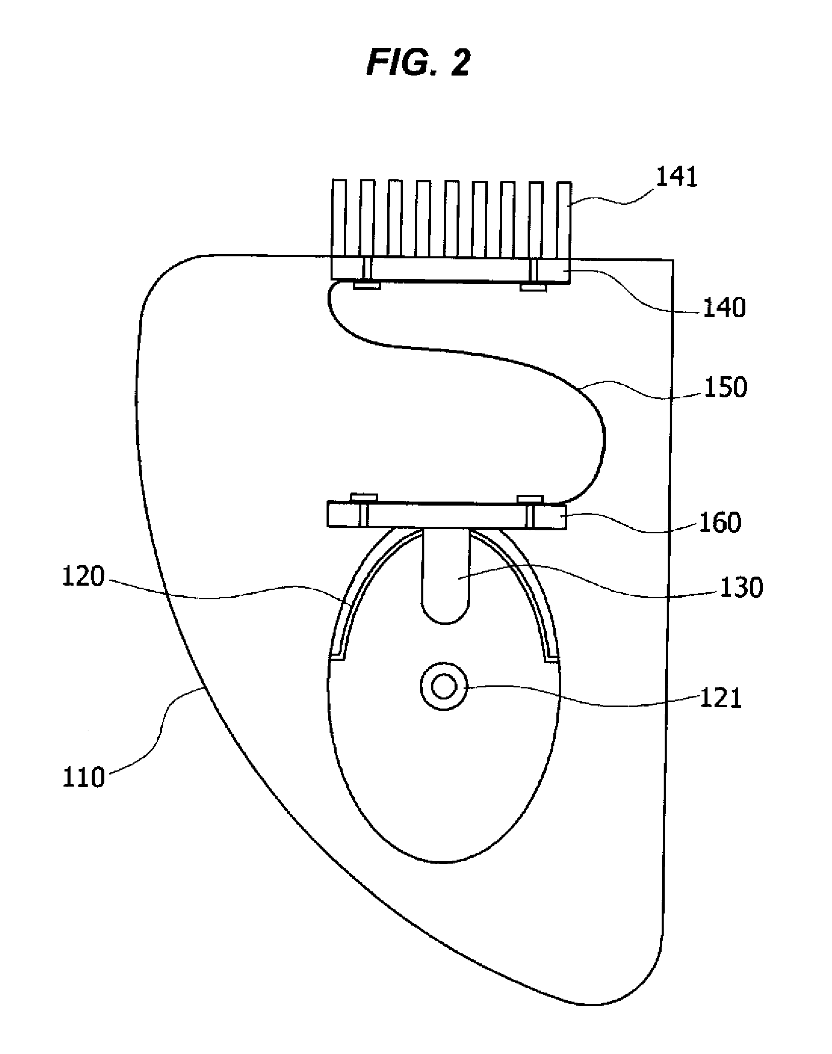
[0025]According to the present invention as described above, the heat of the light source installed on the reflector, which can rotate in leftward/rightward and upward/downward directions, can be transmitted to the external heat sink exposed to the outside of the lamp housing through the heat conduction member and thus the problem of the heat transmis

Problems solved by technology

Consequently, the headlights of a vehicle running along a curved road can disturb an oncoming driver's view of the vehicle on the opposite lane (hereinafter, referred to as “oncoming vehicle”), and the driver himself/herself cannot properly secure clear visibility of the driving curved road so that the driver's safety is often jeopardized or endangered.
Due to these characteristics of the vehicle, the focus of the headlight can be located above or below the normal position at a moment, which is responsible for the glare of the oncoming vehicle or the driver's poor visibility.
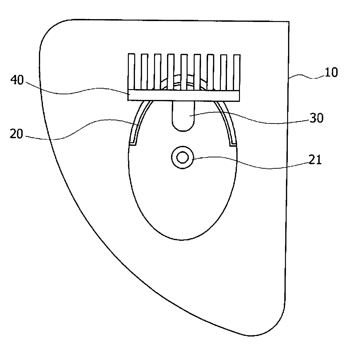
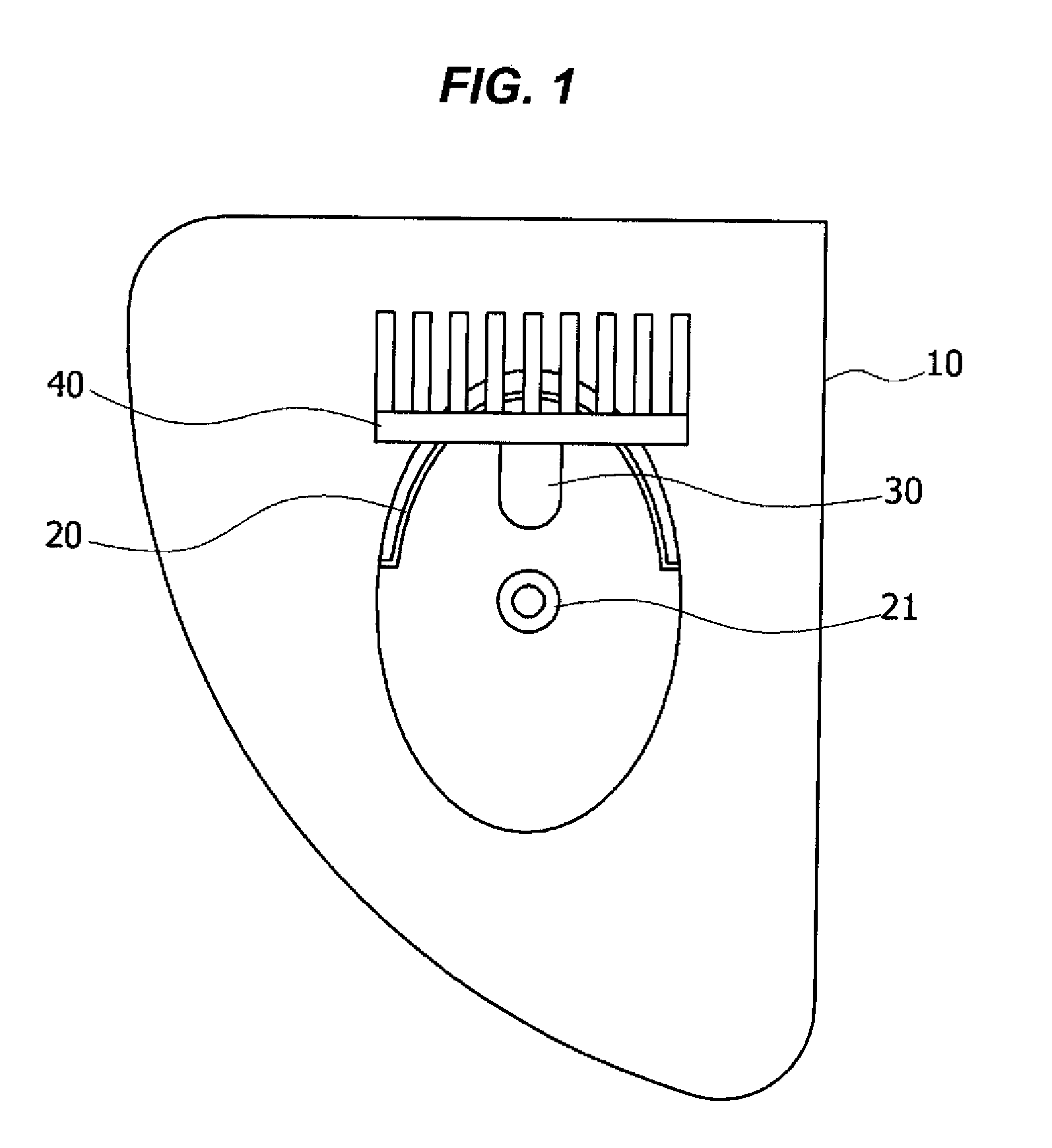
However, since the light source 30 using the LED generates a great deal of heat, the luminous efficiency is

Method used


Image

  • Adaptive Front Light System Having High Heat-Dissipation Efficiency
  • Adaptive Front Light System Having High Heat-Dissipation Efficiency
  • Adaptive Front Light System Having High Heat-Dissipation Efficiency

Examples


Embodiment Construction

[0032]Reference will now be made in detail to various embodiments of the present invention(s), examples of which are illustrated in the accompanying drawings and described below. While the invention(s) will be described in conjunction with exemplary embodiments, it will be understood that present description is not intended to limit the invention(s) to those exemplary embodiments. On the contrary, the invention(s) is / are intended to cover not only the exemplary embodiments, but also various alternatives, modifications, equivalents and other embodiments, which may be included within the spirit and scope of the invention as defined by the appended claims.

[0033]FIG. 2 is a schematic view illustrating the heat sink structure of an adaptive front light system (AFLS) according to an exemplary embodiment of the present invention; FIG. 3 is a perspective view illustrating the structure of a heat conduction member according to the present invention; FIG. 4 is a schematic view illustrating th...


PUM


Abstract

An adaptive front lighting system (AFLS) having a high heat-dissipation efficiency increases heat-dissipation efficiency of a light emitting diode (LED) to improve durability in headlamps which use LEDs as a light source and have a variable illumination angle according to conditions. The AFLS includes a lamp housing, a reflector installed in the lamp housing and rotatable around a rotational axle formed at the lamp housing, a light source installed in the reflector to emit light, an external heat sink installed at an external surface of the lamp housing so as to dissipate heat towards outside of the lamp housing, and/or a heat conduction member connecting the light source and the external heat sink so as to transfer the heat of the light source to the external heat sink. The heat conduction member is flexibly transformed in response to a movement of the reflector and the light source.

Description

CROSS-REFERENCE TO RELATED APPLICATION[0001]This application claims the benefit and priority of Korean Patent Application No. 10-2008-0042319 filed May 7, 2008, the entire contents of which applications is incorporated herein for all purposes by this reference.BACKGROUND OF THE INVENTION[0002]1. Field of the Invention[0003]The present invention relates to an adaptive headlight system of a vehicle, and more particularly to an adaptive front light system (AFLS) having high heat-dissipation efficiency, which increases heat-dissipation efficiency of a light emitting diode (LED) to improve durability in a headlight, which uses the LED as a light source and has a variable illumination angle according to conditions.[0004]2. Description of Related Art[0005]In general, headlights mounted on a vehicle have fixed illumination angle, and thus always illuminate the road ahead of the vehicle regardless of the driving conditions.[0006]Consequently, the headlights of a vehicle running along a curve...

Claims


Application Information

Patent Timeline
IPC IPC(8): H01J7/24
CPCF21S48/115F21S48/325F21V29/76F21V29/004F21V29/02F21S48/328F21S45/43F21S45/50F21S45/48F21V29/71F21V29/67F21S41/151B60Q1/08B60Q1/10B60Q1/12B82Y20/00
Inventor LEE, DAE MINLIM, JUNG WOOK
Owner HYUNDAI MOTOR CO LTD
Why Eureka
Try Eureka