Control switch for controlling magnetic line of force

a technology of control switch and magnetic line, which is applied in the direction of magnetic/electric field switch, magnetic movement switch, electrical apparatus, etc., to achieve the effect of not easily damaged and cost increase of the control circui

Inactive Publication Date: 2009-11-12
CHAO LI MING
View PDF0 Cites 6 Cited by
  • Summary
  • Abstract
  • Description
  • Claims
  • Application Information

AI Technical Summary

Benefits of technology

[0008]One particular aspect of the present invention is to provide a control switch for controlling magnetic line of force. It does not require a magnetic spring switch. The problems of the glass shell of the magnetic spring switch being broken, the spring flake being shifted and displaced to the wrong location, and the magnetic spring switch being interfered by a magnetic element and subsequently leading to erroneous operations are solved. The control switch is not easily damaged, does not fail easily, and it can be applied with those electronic elements that needs limited amount of current or larger amount of current. Thereby the electronic elements can be flexibly selected. The control circuit does not need to be changed, so the cost associated with the control circuit is not increased. The inner and outer wall of the housing does not require through hole for moving the control part.

Problems solved by technology

The problems of the glass shell of the magnetic spring switch being broken, the spring flake being shifted and displaced to the wrong location, and the magnetic spring switch being interfered by a magnetic element and subsequently leading to erroneous operations are solved.

Method used


Image

  • Control switch for controlling magnetic line of force
  • Control switch for controlling magnetic line of force
  • Control switch for controlling magnetic line of force

Examples


Embodiment Construction

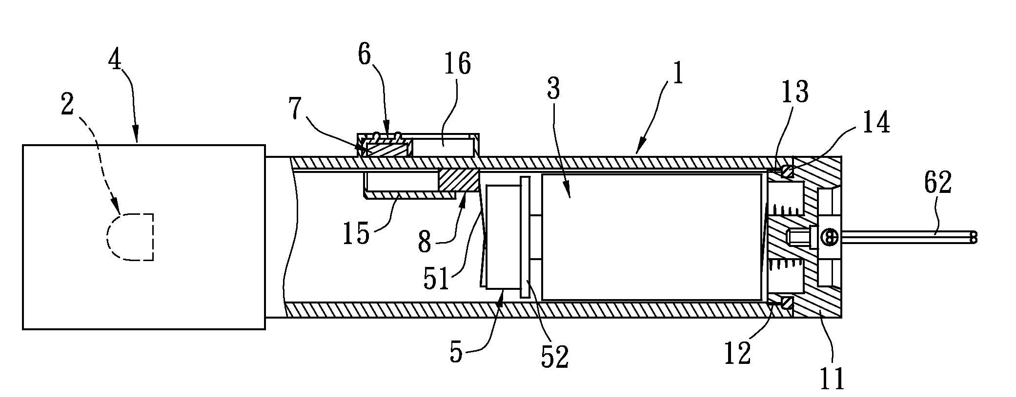
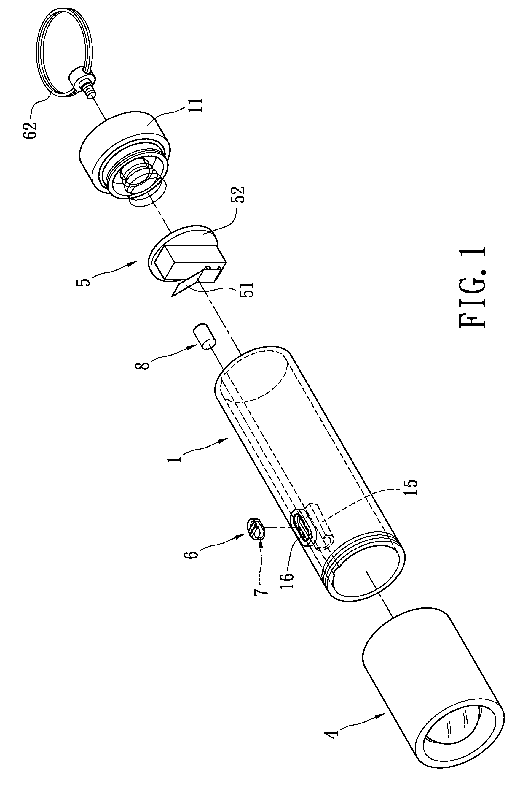
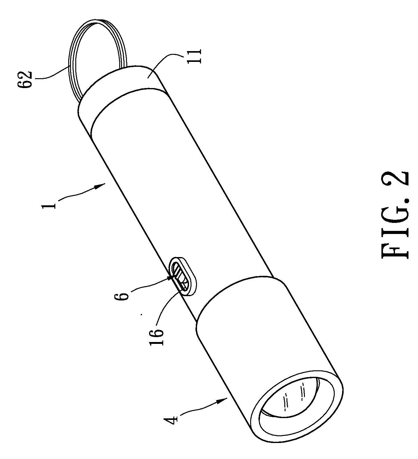
[0028]Reference is made to FIGS. 1-4. The control switch for controlling magnetic line of force is applied to a flashlight, a headlamp, a bicycle lamp, an electric switch, or a laser target equipment for controlling the turning of on or off for electronic element (such as a light source). In this embodiment, the electronic equipment or the electrical equipment is a flashlight. The flashlight has a housing 1, a light source 2, and an electric power 3. The housing 1 is a hollow shell, and its outline is not limited to a specific one. The front side of the housing 1 is located with a lamp head cover 4. The lamp head cover 4 is connected with the front side of the housing 1. The rear side of the housing 1 is attached with a rear cover 11 by screw. The rear cover 11 uses the outer screw thread 12 in combination with the inner screw thread 13 located on the inner wall of the rear side of the housing 1, so that the rear cover 11 is connected with the rear side of the housing 1 for enclosin...


PUM


Abstract

A control switch for controlling magnetic line of force is applied to a switch of an electronic equipment or an electrical equipment. The control switch includes a controlled switch, a control part, a first magnetic element, and a second magnetic element. The control switch is located in the housing of the electronic equipment or the electrical equipment. The control switch is electrically connected with the circuit loop of the electronic equipment or the electrical equipment. The control part is located on the exterior of the housing and is movable. The first magnetic element is installed on the control part. The second magnetic element is movably installed in the housing. The second magnetic element corresponds to the contact flake of the controlled switch. The first magnetic element and the second magnetic element can selectively generate a magnetic line of force reaction.

Description

BACKGROUND OF THE INVENTION[0001]1. Field of the Invention[0002]The present invention relates to a control switch for controlling magnetic line of force; in particular, the present invention relates to a control switch that is applied to electronic equipments or electrical equipments such as a flashlight, a headlamp, a bicycle lamp, an electric switch, or a laser target equipment for controlling the on or off of the power thereof.[0003]2. Description of Related Art[0004]Flashlights or headlamps are one kind of lighting equipment for lighting when guards are patrolling, occurrence of power failure, or conditions of darkness. The flashlights and headlamps usually use a dry cell or a battery as the power source to prevent the flashlights and headlamps from being affect by power outages, so as to meet the requirements for sudden or emergency usage.[0005]In order to meet the requirement of being water-proof, the housing of the flashlights is designed as a structure without through holes,...

Claims


Application Information

Patent Timeline
Patent Type & Authority Applications(United States)
IPC IPC(8): H01H36/00
CPCH01H36/0073
Inventor CHAO, LI-MING
Owner CHAO LI MING
Why Eureka
Try Eureka