Lens device and imaging device

a technology of lens and imaging device, which is applied in the direction of printers, instruments, cameras, etc., can solve the problems of difficulty in focusing at a speed higher than the rotational speed of the motor, complicated mechanism of rotating the focus ring, etc., and achieve the effect of quick focus adjustment and convenient carrying ou

Active Publication Date: 2009-11-12
SONY CORP
View PDF11 Cites 38 Cited by
  • Summary
  • Abstract
  • Description
  • Claims
  • Application Information

AI Technical Summary

Benefits of technology

[0010]According to the present invention, both the focus adjustment in the absence of the fixed end and the focus adjustment in the presence of the fixed end can be easily carried out by switching the positions of the first focus ring, thereby allowing quick focus adjustment to be realized by switching between two modes in response to the situation.

Problems solved by technology

In the case of a lens of a type having a focus ring with a fixed end, a rotated position of the focus ring corresponds to a focus-adjusted state (focal distance) and accordingly adjustment in manual operation can be carried out easily, however, the focus ring with the fixed end should be rotated in agreement with the focus-adjusted state at automatic focusing and therefore, there is a problem that a mechanism of rotating the focus ring is complicated.
In addition, in the case of using an autofocus function, there is a limitation in rotational speed of a motor and therefore, there is a difficulty in focusing at a speed higher than the rotational speed of the motor.

Method used


Image

  • Lens device and imaging device
  • Lens device and imaging device
  • Lens device and imaging device

Examples


Embodiment Construction

[0016]Hereinafter, an embodiment of the present invention is described with reference to FIGS. 1 to 5.

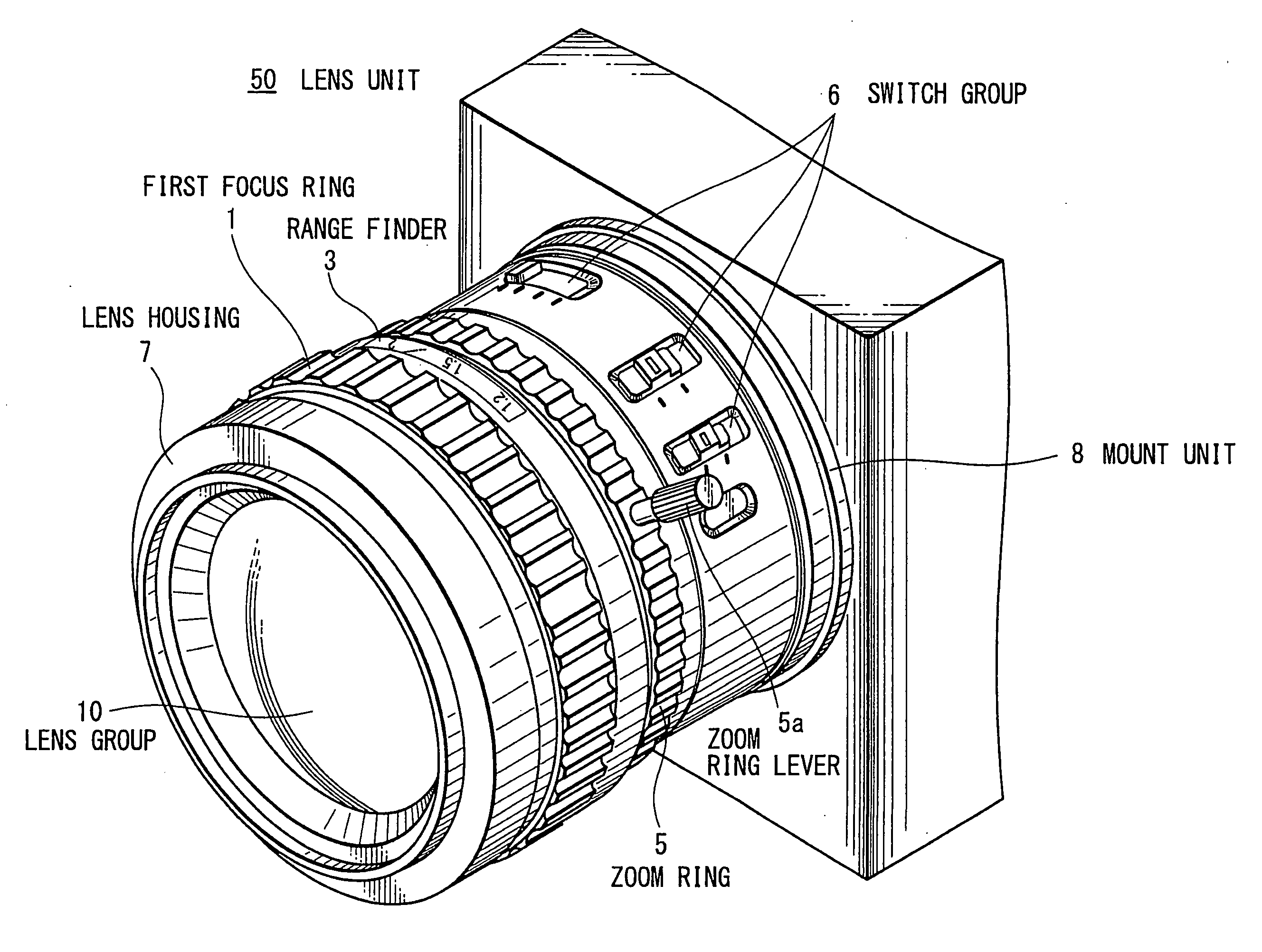
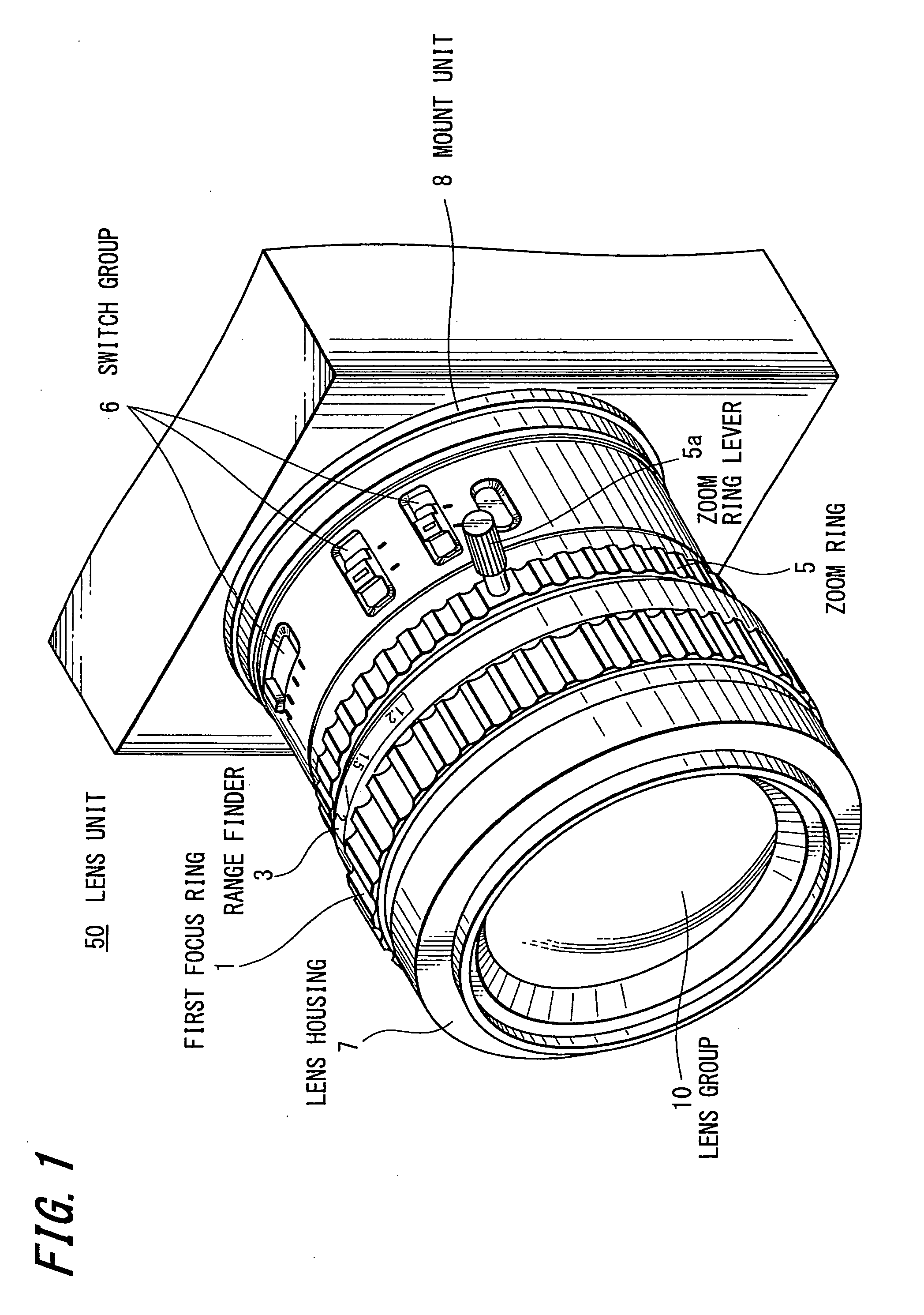
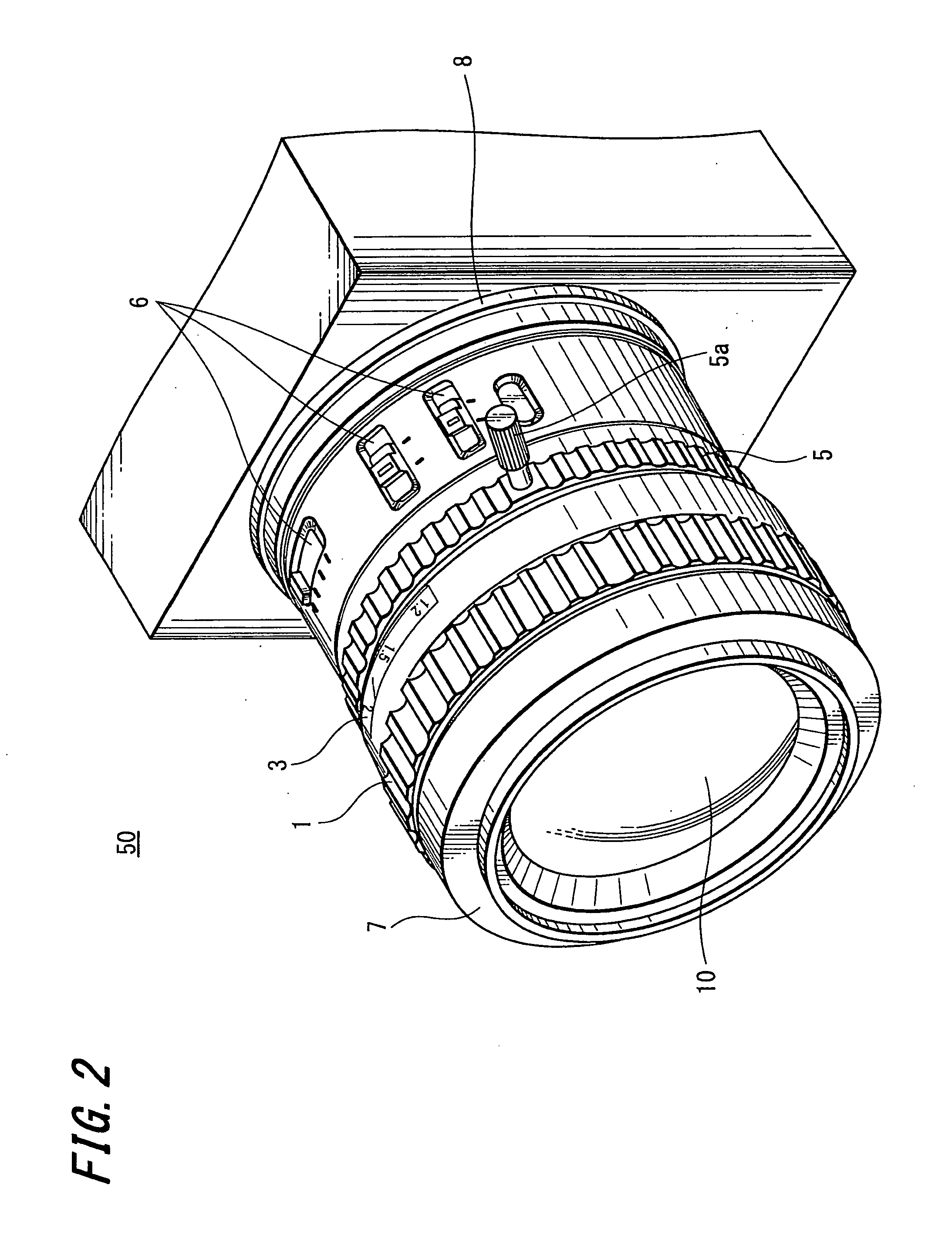
[0017]The embodiment is applied to a video camera with a manual mode in which an autofocus function can be executed and a full-manual mode in which a focusing operation working with a range finder can be executed. FIGS. 1 and 2 are perspective views showing an example of the appearance of a lens unit in a video camera 100. In this embodiment, a focus ring that drives a focus lens can be switched between two positions, front and rear, in the optical axis direction. FIG. 1 shows a state where a focus ring 1 is located at the front in the optical axis direction, while FIG. 2 shows a state where the focus ring 1 is located at the rear in the optical axis direction.

[0018]In FIGS. 1 and 2, a lens unit 50 includes: a lens group 10 including a focus lens (not shown) and the like; a lens housing 7 that holds the lens group 10; a first focus ring 1 that moves the focus lens in the lens group ...


PUM


Abstract

It is intended to carry out a focusing operation suitably in each case of automatic focusing and manual focus adjustment. Therefore, in the present invention, there is provided a first focus ring 1 movable between a first position and a second position on an optical axis. Further, a first rotation-angle detection unit detecting a rotation amount of the first focus ring 1 at the first position, a second focus ring 2 coupled to the first focus ring 1 when the first focus ring 1 is at the first position, and a second rotation-angle detection unit detecting a rotation amount of the second focus ring 2 are provided. When the first focus ring 1 is at the first position, a focus lens is driven based on the rotation amount detected by the first rotation-angle detection unit, and when the first focus ring 1 is at the second position, the focus lens is driven based on the rotation amount detected by the second rotation-angle detection unit.

Description

TECHNICAL FIELD[0001]The present invention relates to a lens device including a focus ring which drives a focus lens, and an imaging device including the lens device.BACKGROUND ART[0002]In the past, in a video camera capable of carrying out comparatively advanced operations for business purposes or the like, a lens housing is provided with a focus ring for moving the position of a focus lens. The focus ring is rotated manually to adjust focus as needed, and the focus lens can be moved forward and backward along an optical axis based on a rotation amount of the focus ring.[0003]In this case, the focus ring does not directly, mechanically work with a focus lens driving mechanism. The rotation amount of the focus ring is electrically detected to drive a motor, thereby moving the lens through the focus lens driving mechanism. That is, there is provided an encoder that detects the rotation amount of the focus ring, and the rotation amount detected by the encoder is changed into a signal ...

Claims


Application Information

Patent Timeline
Patent Type & Authority Applications(United States)
IPC IPC(8): G02B7/02
CPCG02B7/04G02B7/08G02B7/10H04N5/23212H04N5/2254H04N5/2257G03B3/10H04N23/57H04N23/55H04N23/673H04N23/67
Inventor HARADA, KIYOSHITAKEMOTO, SHINJIKIKUCHI, MASAHITO
Owner SONY CORP
Why Eureka
Try Eureka