Power storage device

a technology of power storage and battery cells, applied in the direction of non-aqueous electrolyte cells, cell components, sustainable manufacturing/processing, etc., can solve the problems of uneven temperature distribution in each battery cell, inability to address heat radiation, and difficulty in minimizing the uneven temperature distribution. to achieve the effect of minimizing the uneven temperature distribution

Active Publication Date: 2009-11-12
TOYOTA JIDOSHA KK
View PDF5 Cites 1 Cited by
  • Summary
  • Abstract
  • Description
  • Claims
  • Application Information

AI Technical Summary

Benefits of technology

[0010]The invention provides a power storage device that is adapted to minimize the unevenness of the temperature distribution in a plane perpendicular to the direction in which the components of the power storage device are stacked.
[0019]According to the power storage device described above, because the thickness of the electrolyte layer varies according to the position in the plane perpendicular to the stacking direction (the first position and the second position), the unevenness of the temperature distribution in the same plane can be minimized. More specifically, because the thickness of the electrolyte layer at the first position is larger than the thickness of the electrolyte layer at the second position at which the heat radiation is higher than that at the first position, the increase of the temperature at the first position is suppressed, whereby the unevenness of the temperature distribution between the first position and the second position is minimized.

Problems solved by technology

However, the structure of the battery unit described in JP-A-2006-173095 does not address the issue of the heat radiation of each battery cell.
Therefore, the heat radiation from each battery cell may be insufficient and it may make the temperature distribution in each battery cell uneven.
In such bipolar batteries, if the separators, etc., have a uniform thickness, it is difficult to minimize the unevenness of the temperature distribution due to the heat radiation differences mentioned above.

Method used


Image

  • Power storage device
  • Power storage device
  • Power storage device

Examples


Embodiment Construction

[0030]Hereinafter, example embodiments of the invention will be described.

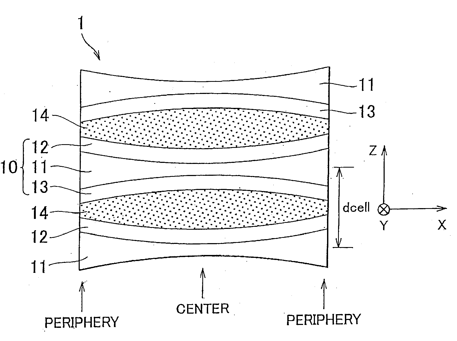
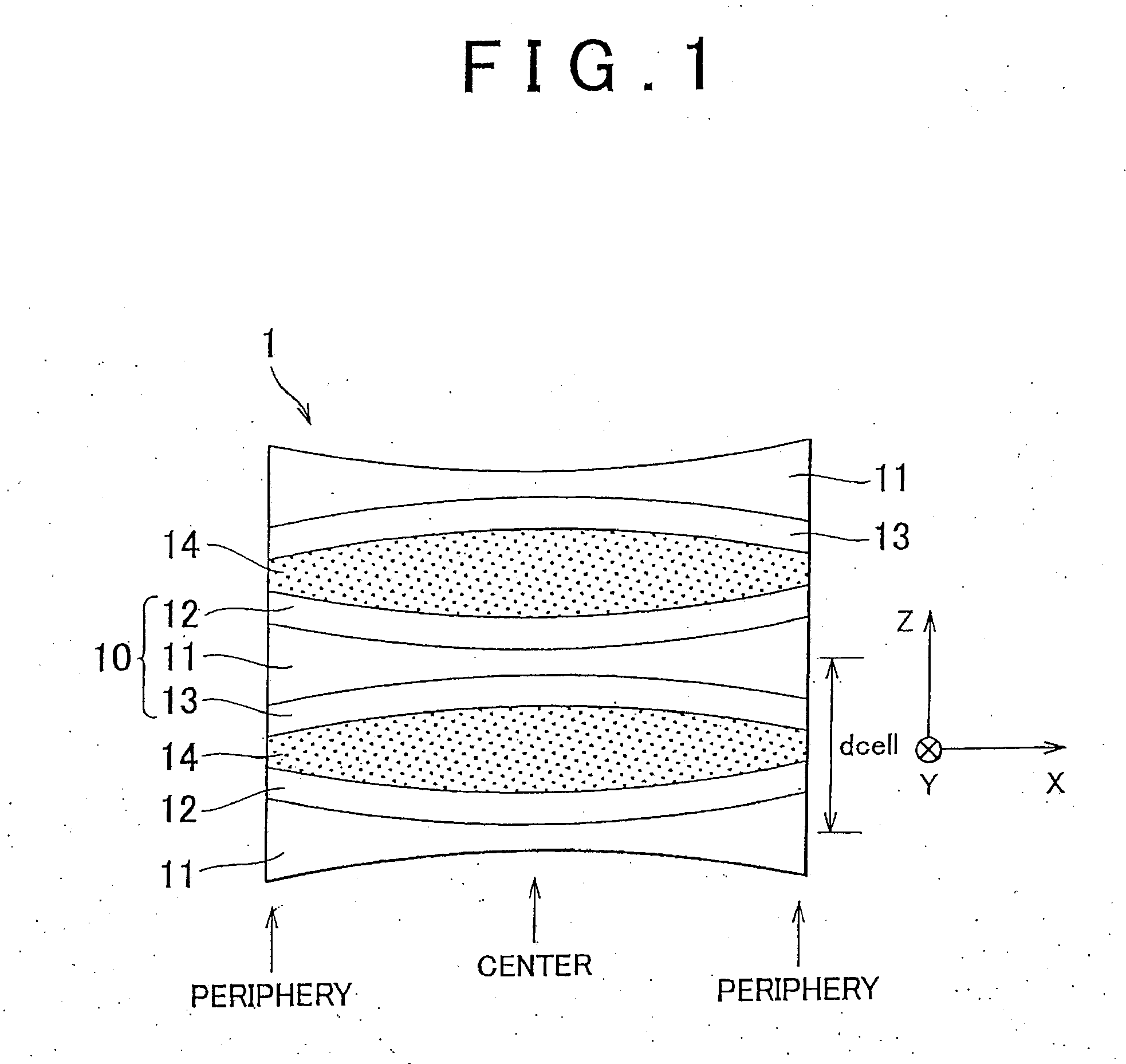
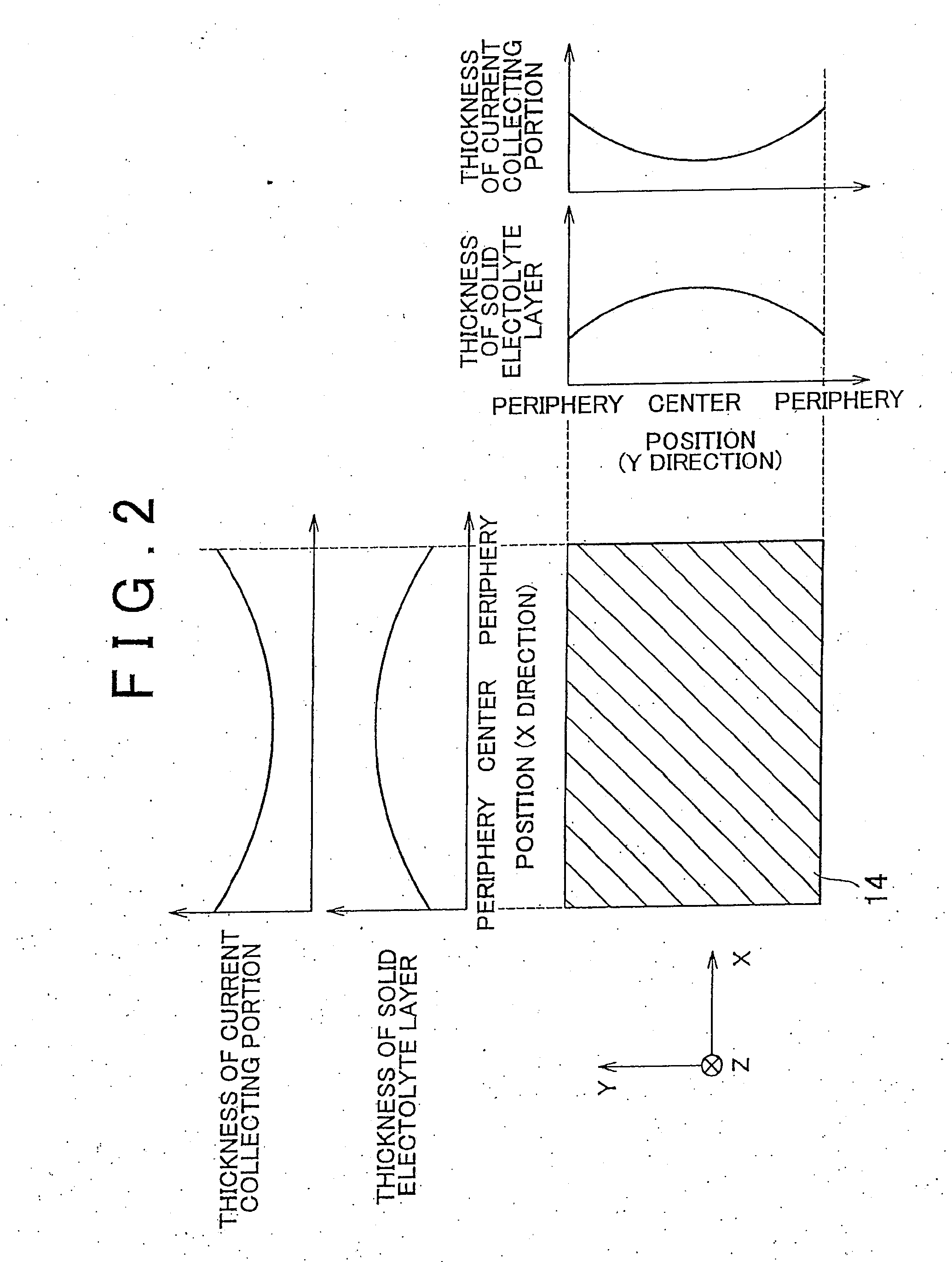
[0031]First, a bipolar battery (secondary battery) according to the first example embodiment of the invention will be described with reference to FIG. 1 and FIG. 2. FIG. 1 is a cross-sectional view of the bipolar battery of the first example embodiment (a portion of the same bipolar battery) which is used as a power storage device. FIG. 2 are a plan view of a solid electrolyte layer incorporated in the bipolar battery of the first example embodiment, charts indicating the thickness of the solid electrolyte layer at each position, and charts indicating the thickness of a current collecting portion at each position.

[0032]Referring to FIG. 1, the bipolar battery 1 of the first example embodiment is constituted of a plurality of bipolar electrodes (“electrodes”) 10 that are stacked on top of each other with solid electrolyte layers 14 interposed in between.

[0033]It is to be noted that while the invention has been ...


PUM

PropertyMeasurementUnit
thicknessaaaaaaaaaa
lengthsaaaaaaaaaa
areaaaaaaaaaaa

Abstract

A power storage device includes: an electrolyte layer; and an electrode consisted of a current collecting portion and an electrode layer, wherein the thickness of the electrolyte layer is larger at a first position in a plane perpendicular to the stacking direction than at a second position where the heat radiation is higher than at the first position, and the thickness of the current collecting portion is smaller at a position corresponding to the first position than at a position corresponding to the second position.

Description

BACKGROUND OF THE INVENTION[0001]1. Field of the Invention[0002]The invention relates to power storage devices (e.g., secondary batteries) having electrolyte layers.[0003]2. Description of the Related Art[0004]Secondary batteries are widely used as the power source for various mobile electronic devices including laptop computers and mobile phones, and secondary batteries are also used as the power source for the power plant of electric vehicles, or the like. With regard to such secondary batteries, various technologies have been proposed to suppress the deterioration of the battery performance due to the variation of the thermal conditions (For example, refer to Japanese patent application publication No. 2006-173095 (JP-A-2006-173095) (Para. 0008 to 0011, Para. 0015-0022, FIG. 1, etc) and Japanese patent application publication No. 2005-340089 (JP-A-2005-340089) (Para. 0029 to 0032, FIG. 3, etc)).[0005]JP-A-2006-173095 describes a battery unit constituted of a plurality of battery ...

Claims


Application Information

Patent Timeline
Patent Type & Authority Applications(United States)
IPC IPC(8): H01M10/50H01M4/02H01M4/62H01M10/04
CPCH01M4/70Y02E60/13H01M10/0585H01M10/18H01M10/282H01M10/3918H01M10/3981H01M10/5004H01M10/5032H01M10/5046H01M2300/0065Y02E60/124Y02E60/126Y02T10/7016Y02T10/7022H01G11/28H01M10/0418H01M10/647H01M10/6551H01M10/613Y02T10/70Y02E60/10Y02P70/50
Inventor NAKAMURA, YOSHIYUKI
Owner TOYOTA JIDOSHA KK
Why Eureka
Try Eureka