Burner with lance

Active Publication Date: 2009-11-12
ANSALDO ENERGIA SWITZERLAND AG
View PDF6 Cites 16 Cited by
  • Summary
  • Abstract
  • Description
  • Claims
  • Application Information

AI Technical Summary

Benefits of technology

[0005]The invention is concerned with the problem of specifying for a burner of the type initially mentioned an improved embodiment which is distinguished, in particular, in that, with it, a relatively good intermixing of th

Problems solved by technology

If, then, a synthesis gas of this type is used as fuel gas in a conventional burner, this may lead to difficulties, since conventional burners are not suitable per se for use with fuel gases having such high reactivity.
Further, these gases have a lower calorific value than natural gas.
Thus, higher mass and volume flows are needed, resulting in changed fuel distribution when fuel is injected from conventional natural gas holes.
With an increased fuel mass flow, however, an undesirable enrichment

Method used


Image

  • Burner with lance
  • Burner with lance

Examples


Example

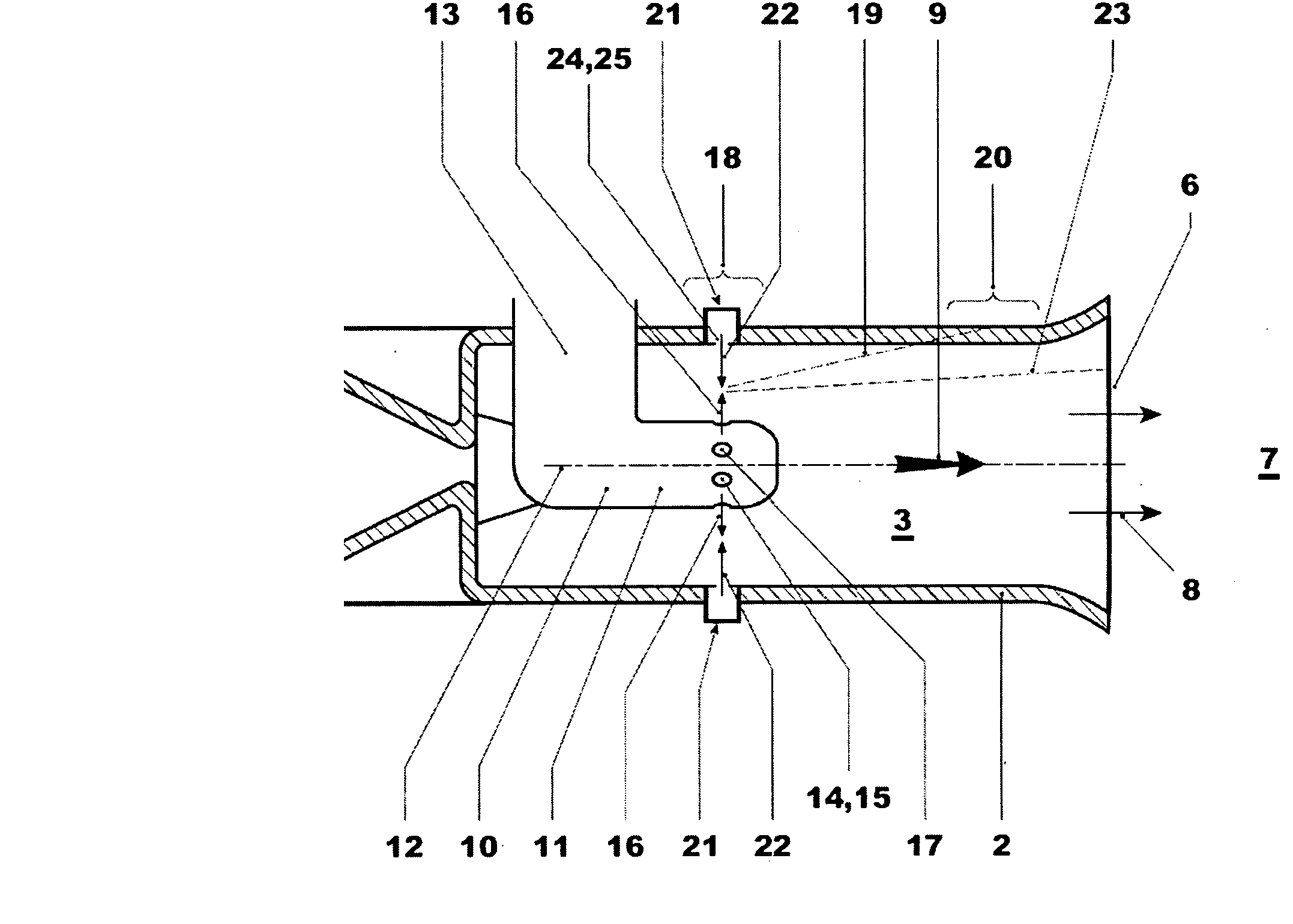
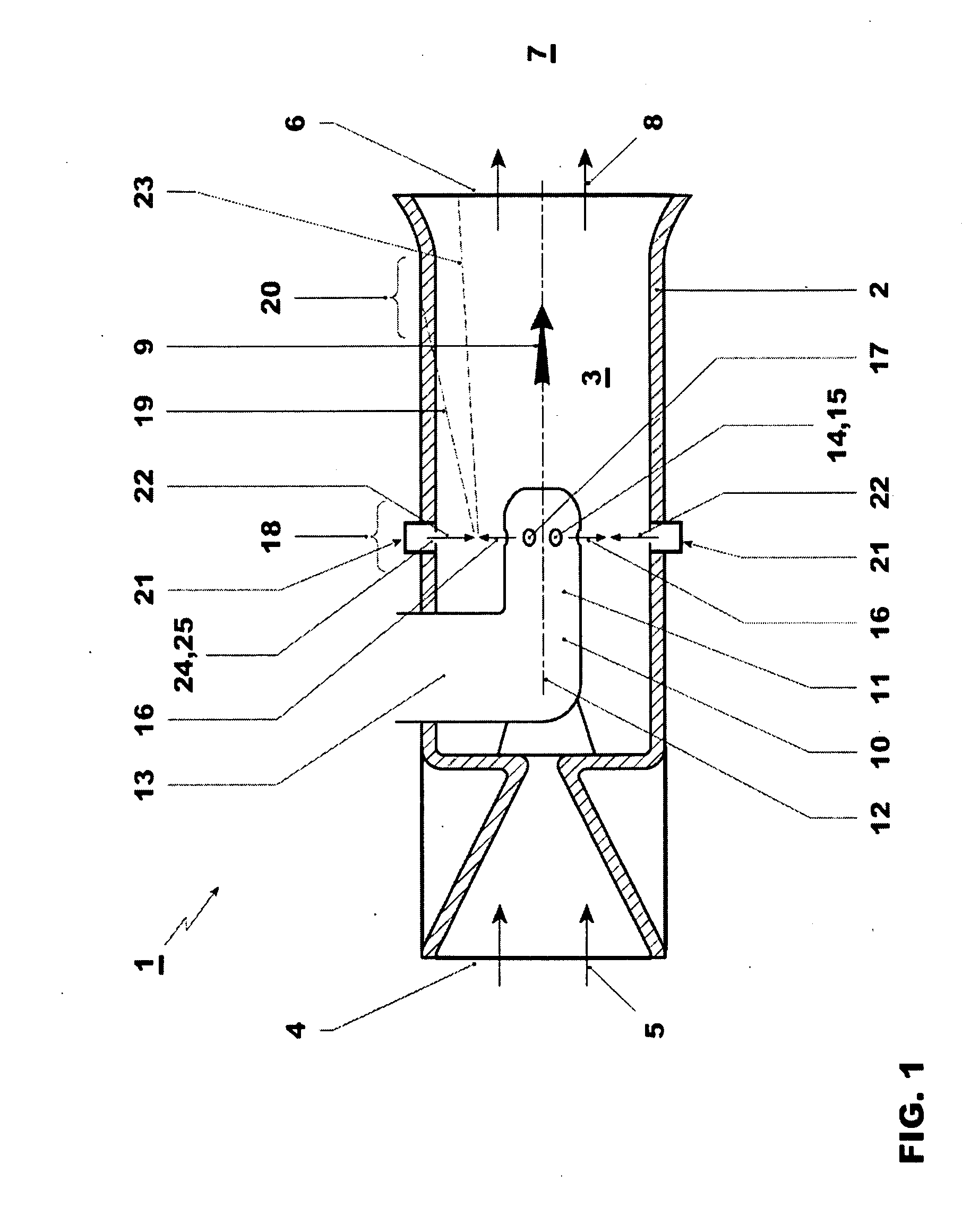
[0012]According to FIG. 1, a burner 1 has a burner wall 2 which laterally delimits a mixing space 3 of the burner 1. The burner 1 usually forms an integral part of a combustion chamber, otherwise not illustrated here, of a gas turbine plant. The burner 1 has an inlet side 4 through which an oxidizer gas, preferably air, enters the mixing space 3. A corresponding oxidizer gas flow is indicated by arrows 5. Furthermore, the burner 1 has an outlet side 6 through which gas flows out of the mixing space 3 and, in particular, enters a combustion space 7 of the combustion chamber. A corresponding gas flow is indicated by arrows 8. The throughflow of the burner 1 or of the mixing space 3 mainly takes place in a longitudinal direction of the burner 1, with the result that a main throughflow direction or main flow direction 9 of the burner is defined, which is indicated in FIG. 1 by an arrow.

[0013]The burner 1, moreover, has a lance 10, with the aid of which a gaseous fuel can be introduced i...


PUM


Abstract

The present invention relates to a burner for a combustion chamber of a gas turbine plant. The burner includes a lance for introducing gaseous fuel into the burner. A shaft of the lance has at least one nozzle for introducing gaseous fuel into the burner. A main injection direction of the respective nozzle is oriented onto a portion of a burner wall. An introduction device for a diverting fluid is provided, which is designed for introducing a diverting fluid counteracting an impingement of the fuel flow on the burner wall.

Description

FIELD OF THE INVENTION[0001]The present invention relates to a burner for a second combustion chamber of a gas turbine plant with sequential combustion having a first and a second combustion chamber, said burner being equipped with a lance.BACKGROUND OF THE INVENTION[0002]Conventional burners as for example known from the DE10128063 may be equipped with a lance for introducing gaseous and / or liquid fuels into the burner. The introduction of fuel via the lance may be utilized, for example, for pilot operation or for stabilizing a combustion reaction in the combustion space of a combustion chamber. Usually, a shaft of such a lance has at least one nozzle for introducing fuel into the burner. An example for such a fuel lance is given in the DE4326802.[0003]Conventional burners preferably operate with natural gas as gaseous fuel. In this case, it is customary to provide the lance shaft along its circumference with a plurality of nozzles, through which the fuel gas can flow out essential...

Claims


Application Information

Patent Timeline
IPC IPC(8): F23C5/06F02C7/22
CPCF23D14/64F23R3/286F23D2900/11001F23D3/20F23D11/101F23D17/002
Inventor CARRONI, RICHARDPOYYAPAKKAM, MADHAVAN NARASIMHANBIALKOWSKI, MICHALWILLETTS, MARK ANDREW
Owner ANSALDO ENERGIA SWITZERLAND AG
Why Eureka
Try Eureka