[0014] In accordance with various aspects of the present invention, a cyclone gasifying combustion burner is configured for use in or coupled to a
solid fuel
biomass device that substantially eliminates various disadvantages of wood-stoves or other
solid fuel combustion devices. For example, an exemplary burner and method of operation can substantially reduce the emission levels of volatile organic compounds (VOC),
particulates and
fly ash as well as the level of
nitrogen oxide (
NOx) and / or all other carbon and volatile gases released during combustion of a
solid fuel.
[0015] In accordance with an exemplary embodiment, a cyclone gasifying combustion burner can be incorporated into or coupled to a device having a
thermal energy source and that can be automatically controlled in a modulated manner to achieve optimum efficiency. Such a cyclone gasifying combustion burner can comprise a fuel bed
support system, such as a pyrolytic fuel bed, that automatically removes ashes from the fuel bed and thereby substantially reduces emission of volatile organic compounds,
particulates, fly-ash,
nitrogen oxides and other pollutants into the
atmosphere. In accordance with another aspect, a cyclone gasifying combustion burner can also be configured such that the fuel bed temperature is starved of combustion air whereby to reduce the temperature of the fuel bed to prevent the fusion of inorganic elements within the
solid fuel. An exemplary cyclone gasifying combustion burner may also be coupled to heating devices for residential, commercial and industrial applications, whereby to replace
fossil fuel dependent heating devices. Such heating devices incorporating the cyclone gasifying combustion burner can also be configured to achieve significant reduction of
greenhouse causing gases.
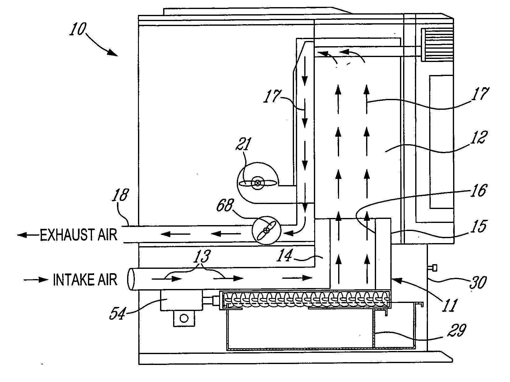
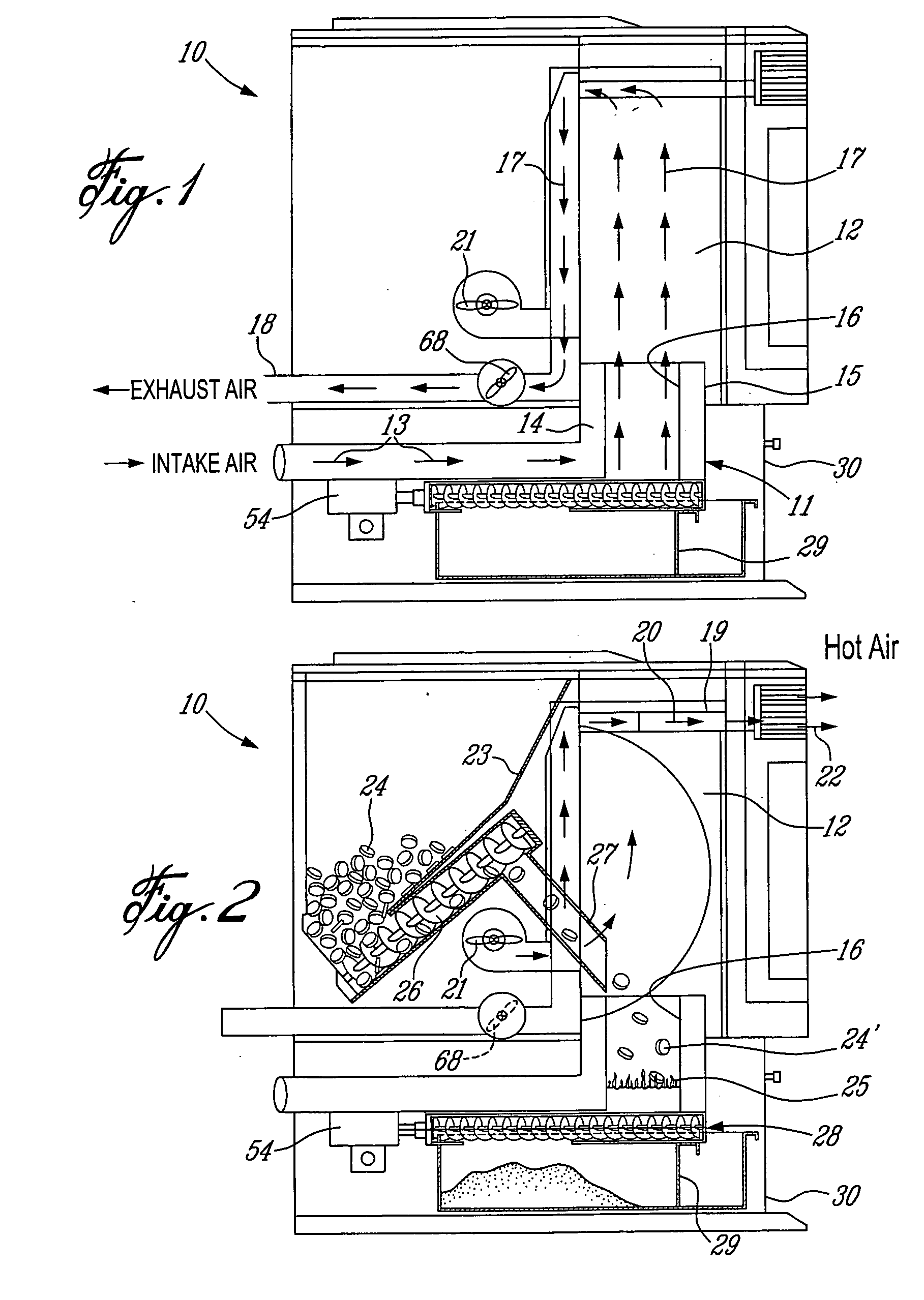
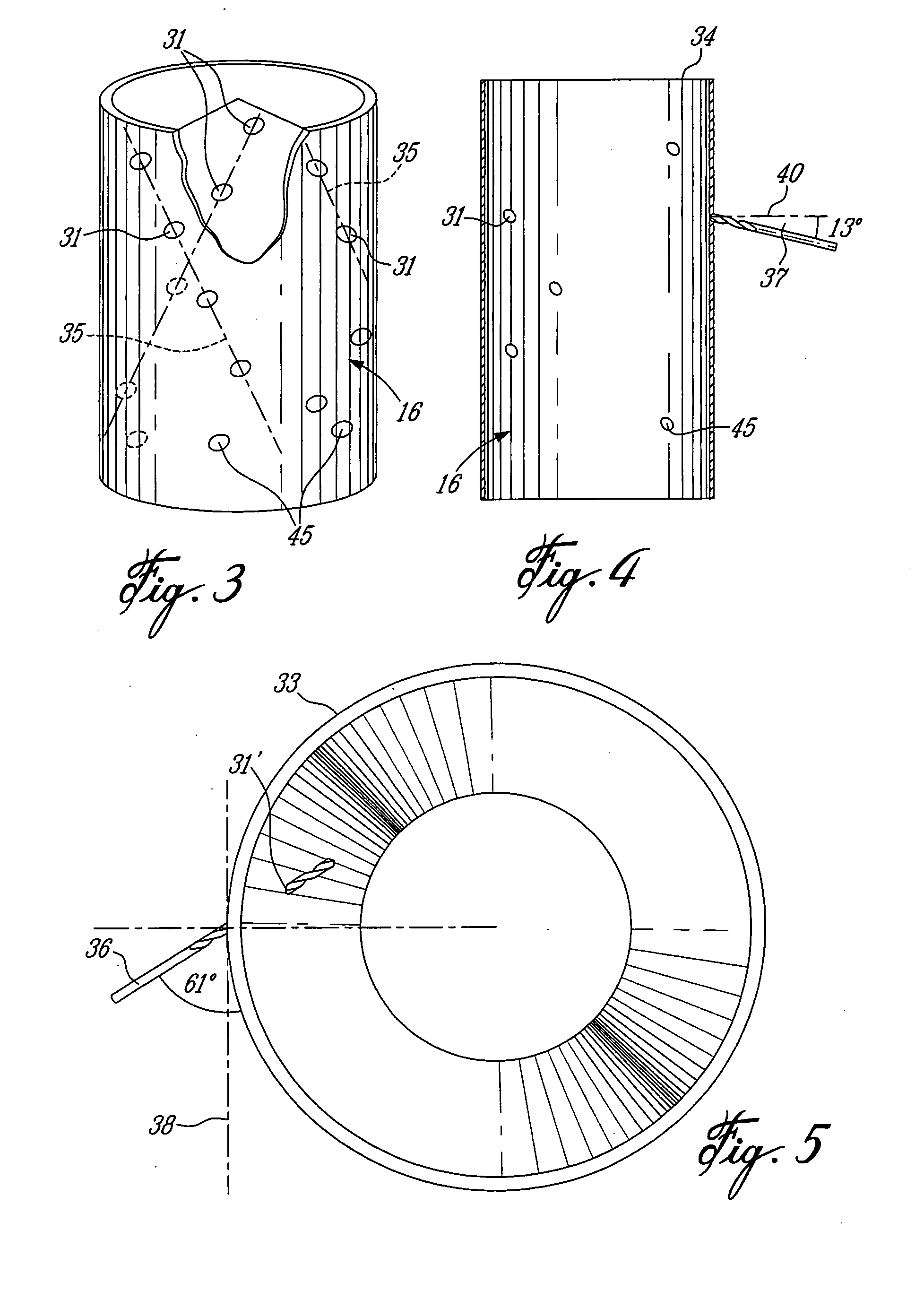
[0016] In accordance with an exemplary embodiment, a cyclone gasifying combustion burner comprises a combustion housing defined by an inner cylindrical wall surrounded by a manifold chamber having combustion air inlet devices and mechanisms. The inner cylindrical wall has air jet holes therein of substantially predetermined
diameter and disposed at a substantially predetermined angle to create an air cyclone flow in a
reaction zone in the inner cylindrical wall and spaced above a lower air-starved gasifying fuel bed thereof. The cyclone flow in the
reaction zone can increase the residency time, turbulence, and mixing of
oxygen and volatile gases to substantially complete combustion of the gases drawn into the reaction zone and causes
suspended particles to gravitate into the fuel bed and thereby substantially reduce the emission of pollutants into the
atmosphere.
[0019] In accordance with another aspect of the present invention, there is provided a method of substantially reducing the emission levels of volatile organic compounds (VOC),
particulates entrained
fly ash, and the level of
nitrogen oxides (
NOX) during combustion of a solid fuel. In accordance with an exemplary embodiment, an exemplary method comprises the steps of feeding the solid or gas fuel in particle-form into an open end of a cyclone gasifying combustion burner and onto a flaming
pyrolysis fuel bed thereof. The fuel bed is disposed below a reaction zone of the burner. The burner has a burner chamber defined by an inner cylindrical wall having a predetermined number of inclined air jet holes of predetermined
diameter and height disposed at substantially predetermined locations to create a cyclone air flow within the reaction zone when combustion air is drawn therethrough. Air is drawn into the burner chamber through the inclined air jet holes whereby to draw combustion gases from the fuel bed into the reaction zone to mix with the cyclone air flow thereby substantially increasing the residency time of the combustion gases in a turbulent, mixing of
oxygen and volatile gases for substantially complete combustion of gases and tars in the reaction zone and to simultaneously precipitate
suspended particles against an inner surface of the inner cylindrical wall to cause at least some of the particles to
agglomerate with other particles to increase their molecular weight and gravitate to the fuel bed.
[0022] In accordance with an exemplary embodiment, there is provided a cyclone gasifying combustion burner having a combustion housing defined by an inner cylindrical wall surrounded by a manifold chamber having a combustion air inlet mechanism or
system. The inner cylindrical wall has air jet holes therein of predetermined diameter and disposed at a predetermined angle to create an air cyclone flow in a reaction zone in the inner cylindrical wall spaced above a lower combustion
gas supply. The cyclone flow in the reaction zone increases the residency time, turbulence, mixing of
oxygen with volatile gases for substantially complete combustion of gases drawn in the reaction zone thereby substantially reducing the emission of pollutants into the atmosphere.
[0023] In accordance with an exemplary embodiment, a method of substantially reducing the emission levels of any one of volatile organic compounds (VOC), particulates, entrained
fly ash, and / or the level of oxygen oxides (
NOx) during combustion of a gas can comprise supplying a combustion gas from below a reaction zone of a cyclone gasifying combustion burner. For example, the burner can comprise a burner chamber defined by an inner cylindrical wall having a substantially predetermined number of inclined air jet holes of substantially predetermined diameter disposed at substantially predetermined locations to create a cyclone air flow within the reaction zone when combustion air is drawn therethrough. The method further comprises drawing air into the burner chamber through the inclined air jet holes whereby to draw the combustion gases into the reaction zone to mix with the cyclone air flow thereby increasing the residency time of the combustion gases, turbulence, and mixing of oxygen with volatile gases for substantially complete combustion of gases in the reaction zone to substantially reduce the emission of pollutants into the atmosphere.

