Coupling device

a coupling device and coupling technology, applied in the direction of couplings, hose connections, borehole/well accessories, etc., can solve the problems of not being able to verify, difficult to position the coiled tubing correctly, and the coupling device is relatively complicated and will not be locked automatically

Inactive Publication Date: 2009-11-12
DEN NORSKE STATS OLJESELSKAP AS
View PDF15 Cites 19 Cited by
  • Summary
  • Abstract
  • Description
  • Claims
  • Application Information

AI Technical Summary

Benefits of technology

[0017]The locking grooves and locking dogs preferably have axial surfaces of angle lower than 90° against the longitudinal axis of the coupling device, thereby the mate and female parts easily can be disconnected by axial tensioning when the locking sleeve is in the lower position.

Problems solved by technology

When joining the coupling parts on deck it will, because of high stiffness of the coiled tubing, be difficult to position the coiled tubing correctly, for which reason the coupling parts are designed for simple alignment into position for joining.
However, the verification cannot be made until after one of the coupling parts, the so-called running tool (11) has been disconnected from the lower coupling part (12), the lock mandrel body.
Said coupling device is relatively complicated and will not be locked automatically by simple joining of the coupling parts.

Method used


Image

  • Coupling device
  • Coupling device
  • Coupling device

Examples


Embodiment Construction

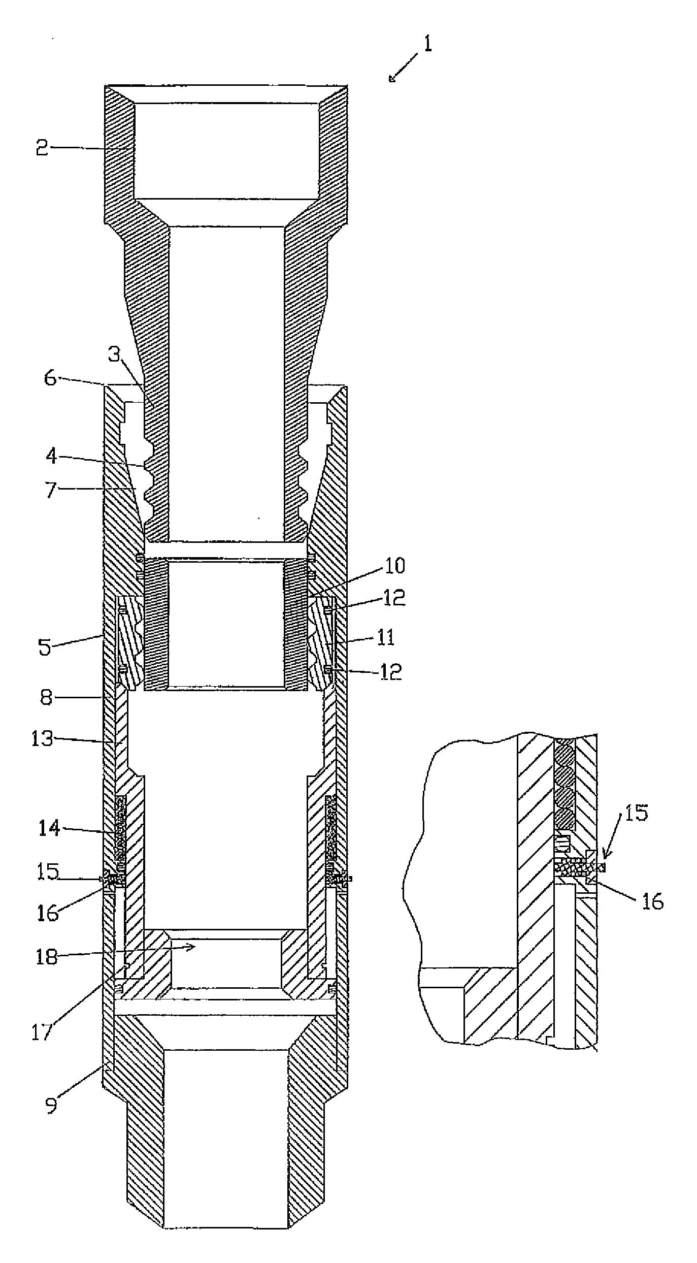
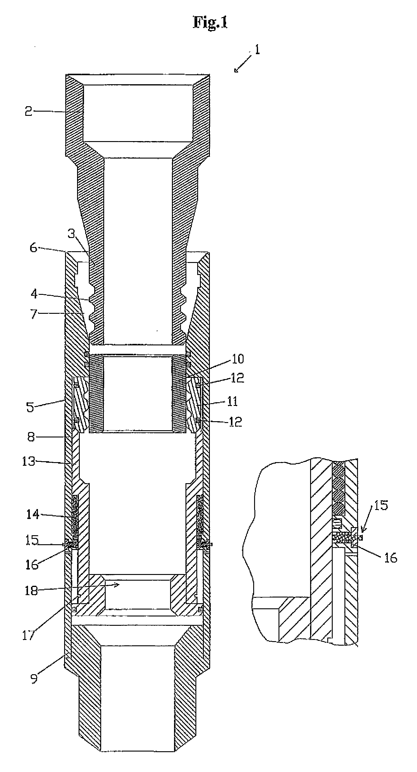
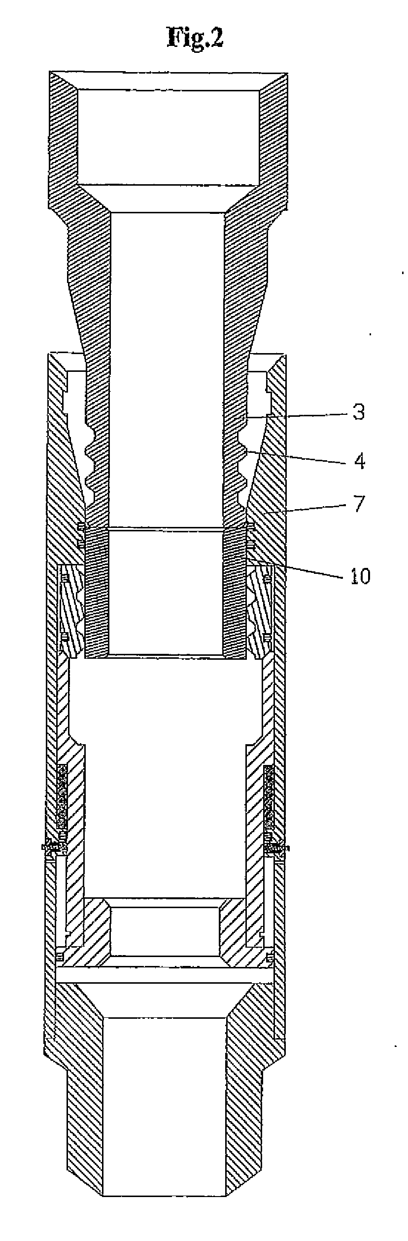
[0026]Reference is first made to FIG. 1, illustrating a coupling device 1 according to the present invention, comprising a male part 2 with a conically shaped stinger part 3 with locking grooves 4, which male part is to be arranged at the end of a coiled tubing (not illustrated). Further, a female part 5 is illustrated, which in an upper end 6 has a receptacle 7 of conical shape adapted for receiving the stinger of the male part, and a house 8 that constitutes an outer part of the female part from the receptacle to a lower end 9. Inside the house of the female part there is an hold-open sleeve 10 arranged towards the upper end, but below the receptacle, which hold-open sleeve is axially displaceable within the house in the direction towards the lower end. Further, locking dogs 11 with spring pre-tensioning 12 are illustrated, which locking dogs are arranged between the house and hold-open sleeve, as the spring pre-tensioning pushes the locking dogs in towards the hold-open sleeve. F...


PUM


Abstract

Coupling device (1) for connection and disconnection of bottomhole equipment, comprising; a male part (2) having a conically shaped stinger (3) with locking grooves (4), which male part is arranged at the end of a coiled tubing; and a female part (5) comprising a receptacle (7) in an upper end (6) and a house (8) that constitutes the outer part of the female part from the receptacle to a lower end (9), which receptacle has conical shape adapted to receive the stinger of the male part, distinguished in that the female part further comprises: a hold open sleeve (10) within the house towards the upper end, adjacent and below the receptacle, which hold open sleeve is axially displaceable in the house in direction towards the lower end and has an internal diameter smaller than the receptacle; locking dogs (11) with a biasing device (12) pushing the locking dogs radially inwards, which locking dogs are arranged between the house and the hold open sleeve; a locking sleeve (13) with a biasing device (14) pushing the locking sleeve towards the upper end, which locking sleeve is arranged axially displaceable in the house below the locking dogs, with internal diameter towards the upper end large enough to receive the hold open sleeve and outer diameter smaller than or equal to the locking dogs in extended position; a verifying bolt (15) with a biasing device (16) pushing the verifying bolt radially inwards, which verifying bolt before joining the male and female parts has an outer end extending out of the house, such that by joining the male and female parts the coupling device will lock automatically, as the hold open sleeve (10) is pushed into the locking sleeve (13) by the stinger, after which the locking dogs (11) are pushed into the grooves (4) of the stinger, after which the locking sleeve is pushed up over the locking dogs locking said locking dogs, after which the verifying bolt once the locking sleeve is in locking position will be pushed into an adapted opening (17) in the locking sleeve, thereby verifying correct locking.

Description

FIELD OF THE INVENTION[0001]The present invention relates to a coupling device for connection and disconnection of bottom-hole equipment, which coupling device comprises a male part that is arranged at the end of a coiled tubing, and a female part. More specifically, the invention relates to a coupling device that locks automatically by joining the male and female parts, the coupling device comprising a device to verify correct locking.BACKGROUND OF THE INVENTION AND PRIOR ART[0002]Several coupling devices for coiled tubing are known. The coupling devices generally comprise a male and a female part, of which the male part can be fastened at the end of a coiled tubing and the female part can be arranged as a part of a bottom-hole equipment that can be brought down with the coiled tubing.[0003]When joining the coupling parts on deck it will, because of high stiffness of the coiled tubing, be difficult to position the coiled tubing correctly, for which reason the coupling parts are des...

Claims


Application Information

Patent Timeline
Patent Type & Authority Applications(United States)
IPC IPC(8): E21B17/046
CPCE21B23/00E21B17/043E21B17/02E21B17/046E21B23/02
Inventor BUCHANAN, ALASTAIRNESVIK, KJELL TOREDAGESTAD, VIBJORN
Owner DEN NORSKE STATS OLJESELSKAP AS
Why Eureka
Try Eureka