Multi-group transmission of a motor vehicle

a multi-group transmission and motor vehicle technology, applied in the direction of gearing control, mechanical equipment, gearing, etc., can solve the problems of unsatisfactory speed increase or decrease, fuel consumption increase, and limited traction force support to certain gearshifts, so as to reduce speed loss, improve driving performance, and increase shift and driving comfort

Inactive Publication Date: 2009-11-12
ZF FRIEDRICHSHAFEN AG
View PDF12 Cites 12 Cited by
  • Summary
  • Abstract
  • Description
  • Claims
  • Application Information

AI Technical Summary

Benefits of technology

[0023]Advantageously, by virtue of the intermediate gear engagement a significant reduction of speed loss is obtained in all traction gearshifts and thus, the resulting driving performance is improved along with greater shift and driving comfort. Since the rotating masses to be synchronized can be braked by the intermediate gear, the transmission brake usually provided for braking those masses in upshift processes can be omitted, whereby further costs, fitting space and weight are saved or reduced. In addition oscillations and jerky shifts are effectively reduced because during the gearshift process the drivetrain remains under load at all times due to the intermediate gear, and this additionally increases the shifting comfort.
[0024]With the upstream change-under-load clutches, which ...

Problems solved by technology

Since the vehicle is rolling during the traction force interruption, undesired speed increases or decreases can occur.
In addition fuel consumption can increase.
However, the traction force support is limited to certain gearshifts.
But in the case of a multi-group transmission with a fine gradation and a large number of gears, traction force interruptions in...

Method used


Image

  • Multi-group transmission of a motor vehicle
  • Multi-group transmission of a motor vehicle
  • Multi-group transmission of a motor vehicle

Examples


Embodiment Construction

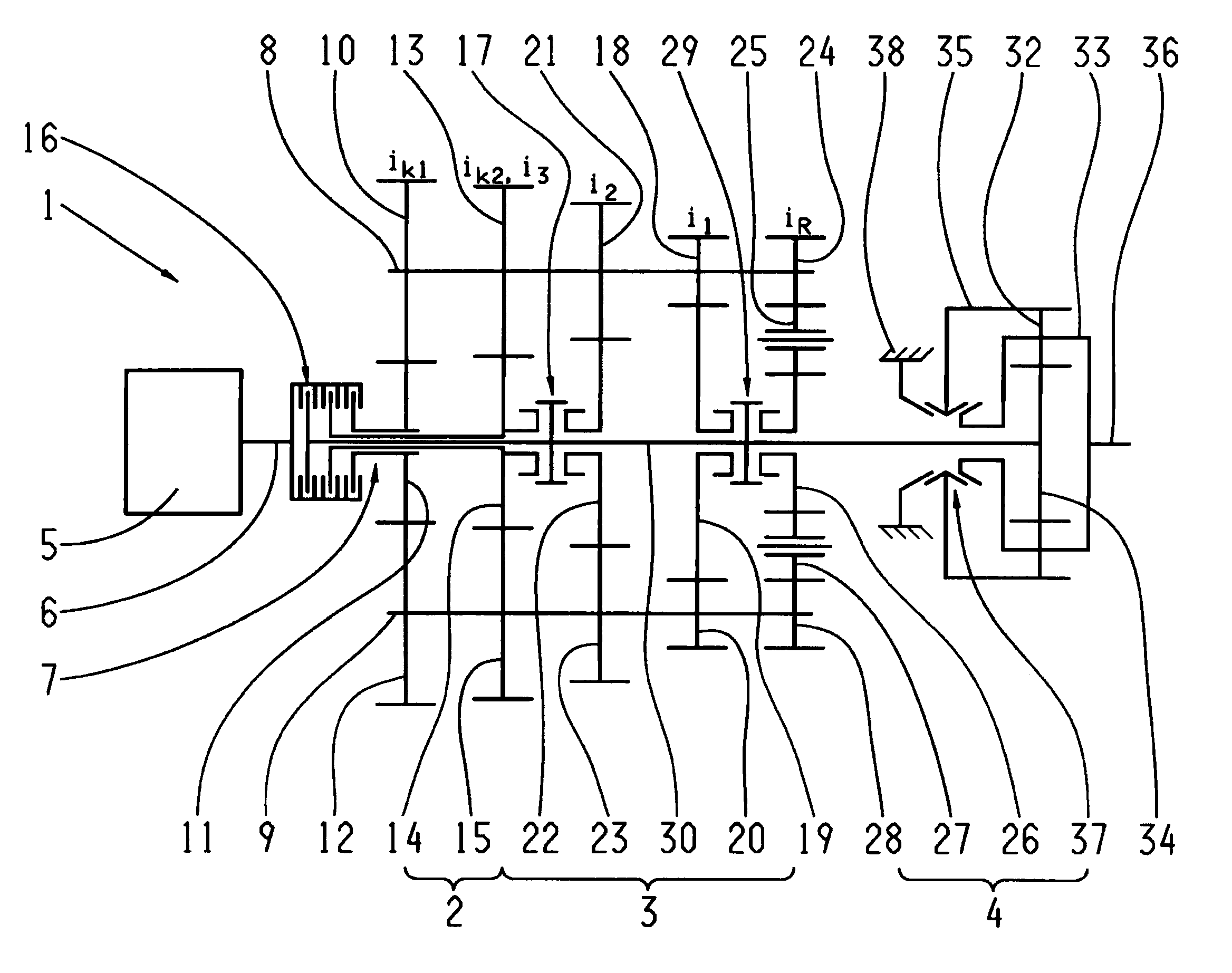
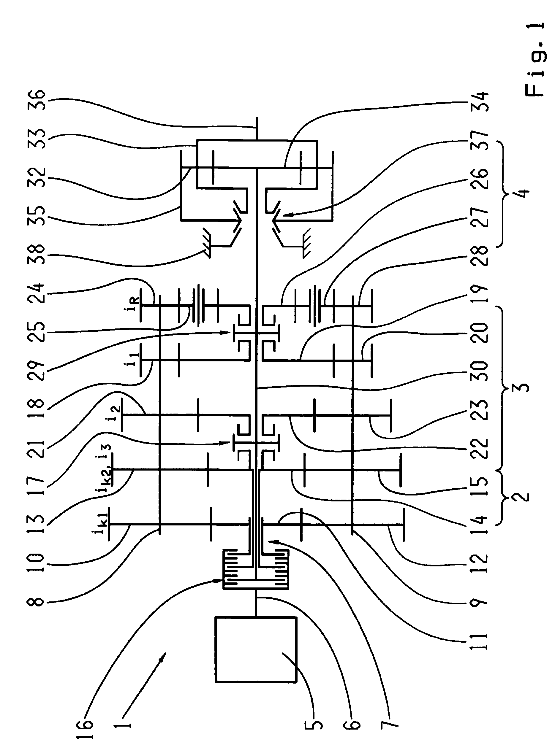
[0029]FIG. 1 shows an automated multi-group transmission made as a two-countershaft transmission 1 with two parallel rotatably mounted countershafts 8, 9 and three transmission groups 2, 3 and 4 arranged one after another, as can be provided for example in the drivetrain of a truck. Such a transmission per se, i.e. without traction force support, is known in particular from the ZF-AS Tronic series, and with a traction-force-supporting direct gear engagement, but with a splitter group that cannot be changed under load, from DE 10 2006 024 370 A1 by the present applicant, mentioned at the beginning.

[0030]The first transmission group 2, arranged on the motor side, is a two-gear splitter transmission. The second, central transmission group 3 is a three-gear main or basic transmission. As the final transmission group 4 on the drive output side, a downstream, two-gear range transmission is provided.

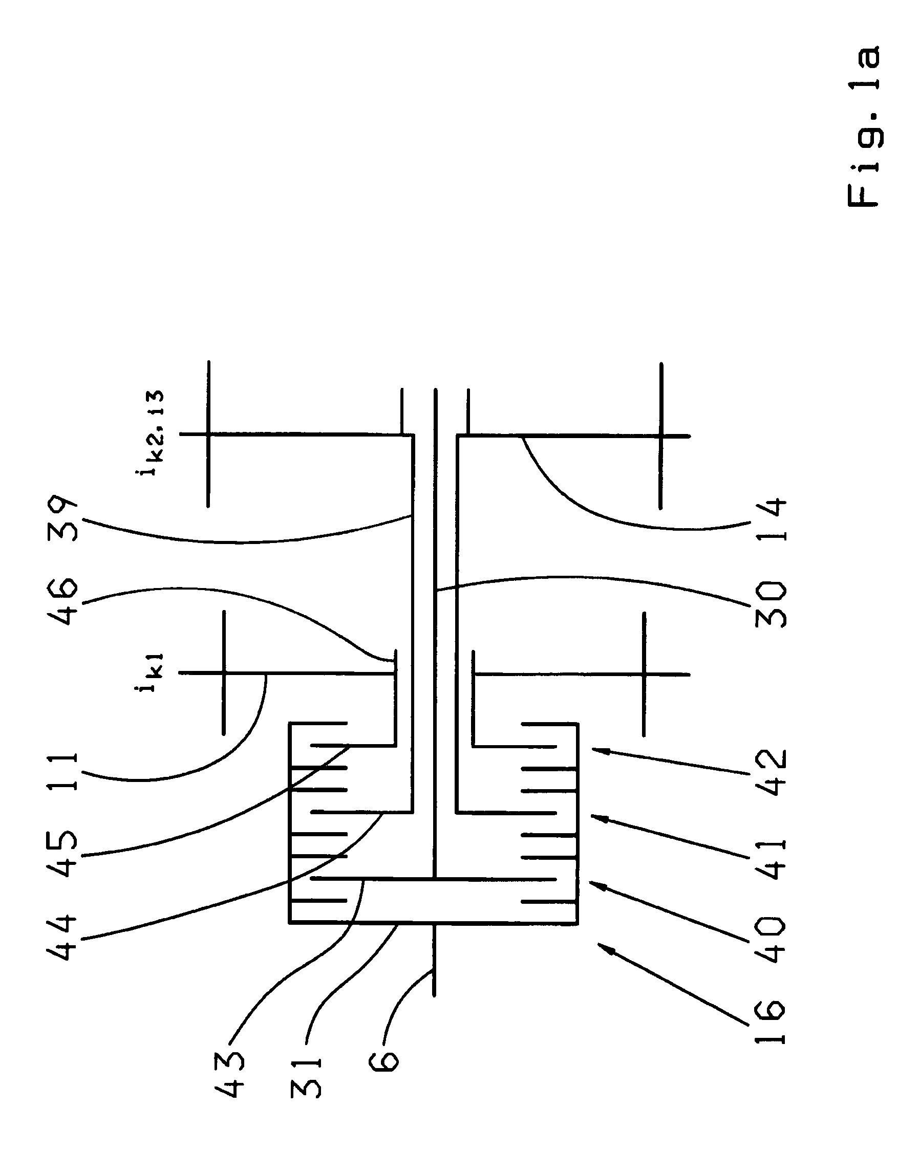
[0031]The splitter group 2 has two gear constants ik1 ik2, each comprising a fixed wheel 10...


PUM


Abstract

The invention concerns a multi-group transmission of a motor vehicle with at least two transmission groups (2, 3) and a method for its operation in which means are provided for supporting the traction force during gearshift operations. In order, by simple, inexpensive and space-saving means, to avoid traction force interruptions during traction gearshifts, a clutch mechanism (16) with three friction clutches (40, 41, 42) is arranged between a drive motor (5) and a transmission input (7), such that the first friction clutch (40) is made as an intermediate-gear clutch connected on its input side to a driveshaft (6) of the drive motor (5) and on its output side to a main transmission shaft (30) which is at least in active connection with a transmission output shaft (36), the second friction clutch (41) is made as a change-under-load clutch connected on its input side to the driveshaft (6) of the drive motor (5) and on its output side to a loose wheel (14) of a second constant (ik2) of a splitter group (2) made as a gear transmission, the third friction clutch (42) is made as a change-under-load clutch connected on its input side with the driveshaft (6) of the drive motor (5) and on its output side with a loose wheel (11) of a first constant (ik1) of the splitter group (2), and such that a direct connection can be formed between the driveshaft (6) of the drive motor (5) and the main transmission shaft (30) by means of the intermediate-gear clutch (40) and the gear constants (ik1, ik2) of the splitter group (2) can be shifted under load by the change-under-load clutches (41, 42).

Description

[0001]This application claims priority from German patent application serial no. 10 2008 001 646.2 filed May 8, 2008.FIELD OF THE INVENTION[0002]The invention concerns a multi-group transmission of a motor vehicle and a method for operating a multi-group transmission of a motor vehicle.BACKGROUND OF THE INVENTION[0003]Multi-group transmissions consist of two or more transmission groups, usually arranged in series, by combining the groups a large number of gears can be produced. Increasingly, they are designed as automated gearshift transmissions consisting, for example of an input group, a main group and a downstream range group. Such transmissions are used particularly in utility vehicles since they provide an especially fine gradation of gears, for example 12 or 16 gears, and are highly efficient. For a smaller number of gears, configurations with only a main group and an input group or a main group and a range group are also possible. Furthermore, compared with manual gearshift t...

Claims


Application Information

Patent Timeline
IPC IPC(8): F16H3/093F16H61/04F16H61/70
CPCF16H3/006F16H3/095F16H37/042F16H37/046Y10T74/19233F16H2061/0425F16H2061/0429Y10T74/19228Y10T477/641F16H61/702
Inventor DITTRICH, ALANHOFFMANN, RAYK
Owner ZF FRIEDRICHSHAFEN AG
Why Eureka
Try Eureka