Smoke dust suction device applied to laser surface decontamination

An inhalation device and a technology for fume and dust, which are applied to the cleaning method using tools, the cleaning method using gas flow, the cleaning method and utensils, etc., which can solve the problems of affecting the dust suction effect, reducing the inhalation ability, and unable to effectively remove the dust of the adsorption tube. , to achieve the effect of expanding the vacuuming range, increasing the flow rate, and improving the vacuuming effect.

Pending Publication Date: 2021-06-18
HAINAN NUCLEAR POWER
View PDF0 Cites 2 Cited by
  • Summary
  • Abstract
  • Description
  • Claims
  • Application Information

AI Technical Summary

Problems solved by technology

[0004] The purpose of the present invention is to provide a smoke suction device for laser surface decontamination in view of the deficiencies in the prior art. Through the coordinated design of the housing and the rotating shaft, it effectively solves the problem that the dust in the existing adsorption tube cannot be effectively removed, causing inhalation Decreased capacity, affecting the vacuuming effect

Method used


Image

  • Smoke dust suction device applied to laser surface decontamination
  • Smoke dust suction device applied to laser surface decontamination
  • Smoke dust suction device applied to laser surface decontamination

Examples


Embodiment Construction

[0029] In order to better understand the technical content of the present invention, specific embodiments are provided below, and the present invention is further described in conjunction with the accompanying drawings.

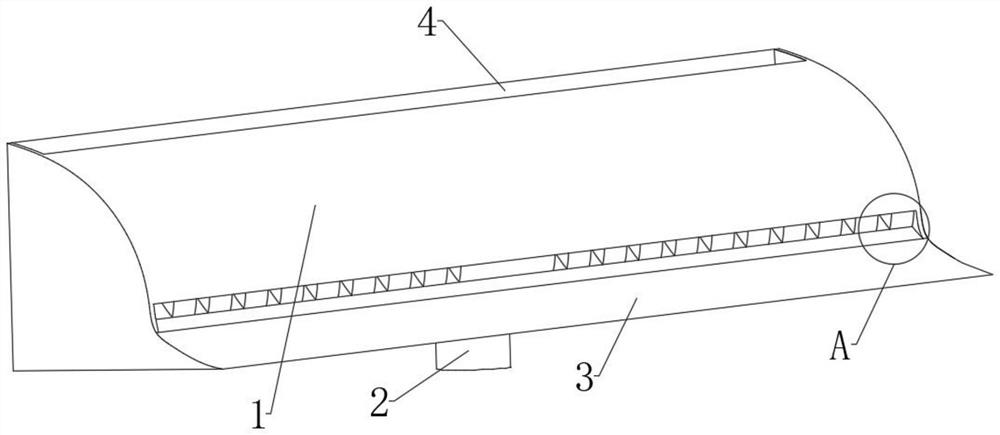
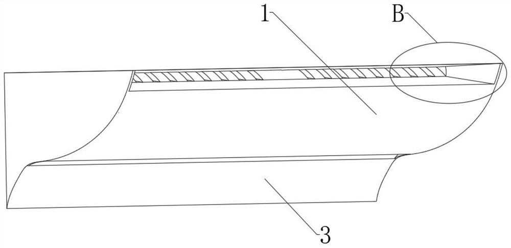
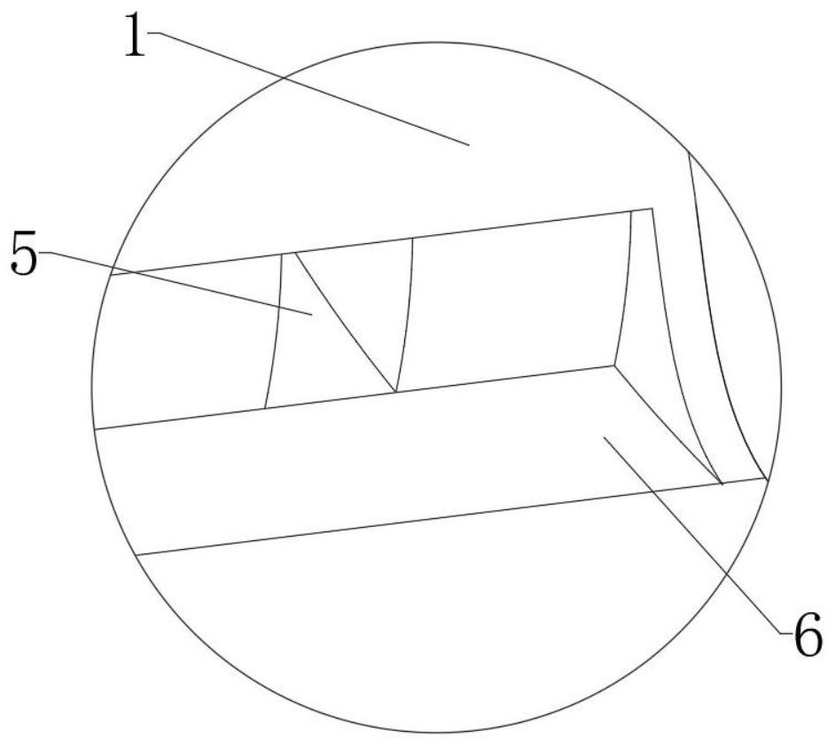
[0030] see Figures 1 to 7 , the present invention provides a smoke suction device applied to laser surface decontamination, comprising a housing 1 and a rotating shaft 8, a circular cavity 12 is arranged transversely in the housing 1, and the cavity 12 is arranged along the length direction of the housing 1, The top, the front side and the middle of the bottom of the housing 1 are respectively provided with a first guide groove 4, a second guide groove 6 and an air outlet 10, specifically, the first guide groove 4 is arranged on the top of the housing 1 the rear side of the housing, the second guide groove 6 is arranged at the bottom of the front side of the housing 1, the first guide groove 4 and the second guide groove 6 are arranged along the length direc...


PUM


Abstract

The invention relates to a smoke dust suction device applied to laser surface decontamination. The smoke dust suction device comprises a shell and a rotating shaft, wherein a circular cavity is formed in the shell, and a first flow guide groove, a second flow guide groove and an air outlet are formed in the middle of the top, the middle of the front side and the middle of the bottom of the shell correspondingly; a plurality of first tangential air inlets and second tangential air inlets are formed in the air outlet ends of the first flow guide groove and the second flow guide groove at intervals correspondingly, the first tangential air inlets and the second tangential air inlets deviate from the axis part of the cavity, the rotating shaft is arranged in the cavity, and the two ends of the rotating shaft are rotationally connected with the shell correspondingly; and a first spiral brush and a second spiral brush are arranged at the two sides of the rotating shaft respectively, and the rotating directions of the first spiral brush and the second spiral brush are opposite. According to the smoke dust suction device, through the cooperative design of the shell and the rotating shaft, the problems that because dust in an existing adsorption pipe cannot be effectively removed, the suction capacity is reduced and the dust collection effect is affected are effectively solved.

Description

technical field [0001] The invention belongs to the technical field of smoke and dust suction devices, in particular to a smoke and dust suction device applied to laser surface decontamination. Background technique [0002] During the production process of nuclear power plants, the surface of the workpiece will be polluted by nuclear radiation. It is necessary to install the workpiece in a closed space, and then use laser to remove the nuclear radiation material on the surface of the workpiece. In this process, a large amount of nuclear radiation dust will be generated. It needs to be sucked up and transported to the filter device in time to avoid direct discharge into the air and cause plant pollution. [0003] However, in the current prior art, the adsorption tube is usually fixedly installed in the sealed space, and a number of suction ports are arranged on one side of the adsorption tube, and a suction device (such as a fan, etc.) is used to generate a negative pressure ...

Claims


Application Information

Patent Timeline
Patent Type & Authority Applications(China)
IPC IPC(8): B08B5/04B08B1/04B08B13/00
CPCB08B1/04B08B5/04B08B13/00
Inventor 张学文吴淑玉张陈材段淙凯石志彬
Owner HAINAN NUCLEAR POWER
Why Eureka
Try Eureka