Method and Apparatus for Transitioning an Electrically Variable Transmission

a transmission and electrically variable technology, applied in the direction of analogue processes, instruments, etc., can solve the problems of less than optimal shift time and/or shift efficiency of control strategies for executing shifts or transitions in an evt, and it is not easy to easily control battery power independently of output torque, etc., to achieve constant engine speed, reduce shift time, and improve shift efficiency

Inactive Publication Date: 2009-11-12
GM GLOBAL TECH OPERATIONS LLC
View PDF13 Cites 14 Cited by
  • Summary
  • Abstract
  • Description
  • Claims
  • Application Information

AI Technical Summary

Benefits of technology

[0010]Accordingly, a shift control strategy or method is provided for reducing shift time and improving shift efficiency in an electrically-variable transmission or EVT. The control strategy utilizes a plurality of t...

Problems solved by technology

In a mode with three speed DOF, it is generally not possible to easily control battery power independently of output torque.
Howe...

Method used


Image

  • Method and Apparatus for Transitioning an Electrically Variable Transmission
  • Method and Apparatus for Transitioning an Electrically Variable Transmission
  • Method and Apparatus for Transitioning an Electrically Variable Transmission

Examples


Embodiment Construction

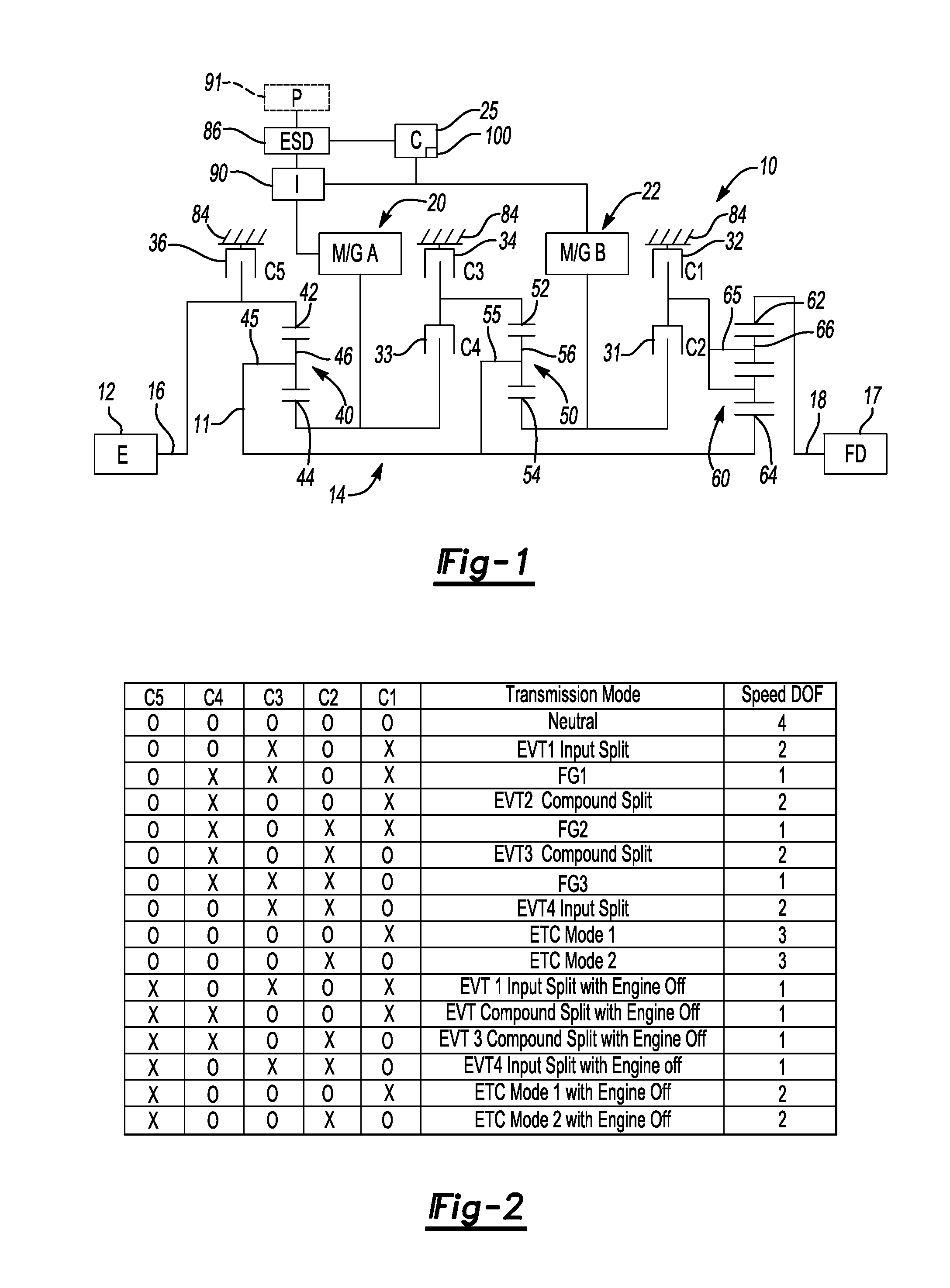
[0027]Referring to the drawings, wherein like reference numbers refer to like components, and beginning with FIG. 1, a powertrain 10 derives propulsive energy or power from any or all of an engine 12, a first motor / generator 20 (also labeled M / G A), and a second motor / generator 22 (also labeled M / G B), as well as from an energy storage device or ESD 86, as will be explained below. The engine 12 has an output shaft or member that serves as an input member 16 of an electrically-variable transmission or EVT 14. The EVT 14 is designed to selectively receive a portion of its driving power from the engine 12 in a plurality of its various transmission states or operating modes, which include a pair of electric torque converter (ETC) modes described below, a pair of input split modes, a pair of compound split modes, and a plurality of fixed gear ratio modes, as will be discussed below with reference to FIG. 2. A final drive unit or assembly 17, abbreviated FD in FIG. 1 for simplicity, is op...


PUM


Abstract

A method is provided for transitioning from an initial to a final transmission mode in an electrically variable transmission (EVT), and includes transitioning to an intermediate mode having an additional speed degree of freedom (DOF), changing a transmission ratio, and engaging a clutch to shift to the final mode. The modes include input and compound split, fixed gear ratio, and electric torque converter (ETC), with and without input from an engine. Output torque is maintained by adjusting a charge on an energy storage device. A brake grounds an input member of the EVT. The EVT has the input member, an output member, a stationary member, and first and second motor/generators. An algorithm transitions between modes by releasing at least one clutch to transition to a mode having an extra speed degree of freedom (DOF), and utilizing the extra speed DOF to change the ratio of the EVT.

Description

TECHNICAL FIELD[0001]The invention relates to a control strategy or method and an apparatus for transitioning between different operating states or modes of an electrically variable transmission (EVT).BACKGROUND OF THE INVENTION[0002]An electrically variable transmission (EVT) typically has an input member connected to an engine, as well as one or two motor / generators that are each selectively connected to different members of multiple gear sets to enable one or more transmission operating modes. The transmission operating modes may include various EVT modes, such as input, output, and / or compound split modes, fixed speed ratio modes, and electric-only (battery powered) or EV modes. An EVT mode is an operating mode in which the speed ratio between an input and an output member of the transmission is determined by the speed of one or both of the motor / generators.[0003]An EVT may improve vehicle fuel economy in a variety of ways. For instance, the engine may be turned off at idle, dur...

Claims


Application Information

Patent Timeline
IPC IPC(8): G06F19/00F16H3/72
CPCB60K1/02Y02T10/6239B60K6/445B60K6/547B60L2240/423B60W10/02B60W10/06B60W10/08B60W10/115B60W20/00B60W2710/0644B60W2710/0666B60W2710/083F16H3/728F16H2037/104F16H2061/6603F16H2200/201F16H2200/2043Y02T10/6269Y02T10/6286Y02T10/642B60K6/365Y02T10/62Y02T10/64B60W20/40
Inventor CONLON, BRENDAN M.SAH, JY-JEN F.
Owner GM GLOBAL TECH OPERATIONS LLC
Why Eureka
Try Eureka