Control unit simulation method, system, and program

a control unit and simulation method technology, applied in the field of control unit simulation method, system and program, can solve the problems of requiring a lot of effort, a lot of work, and a lot of preparation

Active Publication Date: 2009-11-12
IBM CORP
View PDF0 Cites 39 Cited by
  • Summary
  • Abstract
  • Description
  • Claims
  • Application Information

AI Technical Summary

Problems solved by technology

When a number of ECUs are installed in the car, the multi-ECU case, as described above, it becomes very difficult to test at the development stage whether multiple ECUs are properly operating in cooperation with each other.
Thus, preparation for this takes a lot of work.
Thus, much effort is required.
Furthermore, since the test uses the actual ECU, it takes actual time to conduct the test.
Therefore, it takes an enormous amount of time to test many scenarios.
Moreover, the hardware device for emulation of the HILS is generally very expensive.
However, the known SILS only performs software verification on a single function and does not make it possible to achieve SILS for a multi-ECU.
However, it is very difficult or practically impossible to apply such conventional techniques to software simulation of the multi-ECU case.

Method used


Image

  • Control unit simulation method, system, and program
  • Control unit simulation method, system, and program
  • Control unit simulation method, system, and program

Examples


Embodiment Construction

[0038]With reference to the drawings, a configuration and process according to an embodiment of the present invention will be described below. In the following description, unless otherwise noted, the same components are denoted by the same reference numerals throughout the drawings. Note that the configuration and process are described here as one embodiment of the invention. Thus, it should be understood that there is no intention to interpret the present invention so as to limit the technical scope of the present invention to this embodiment.

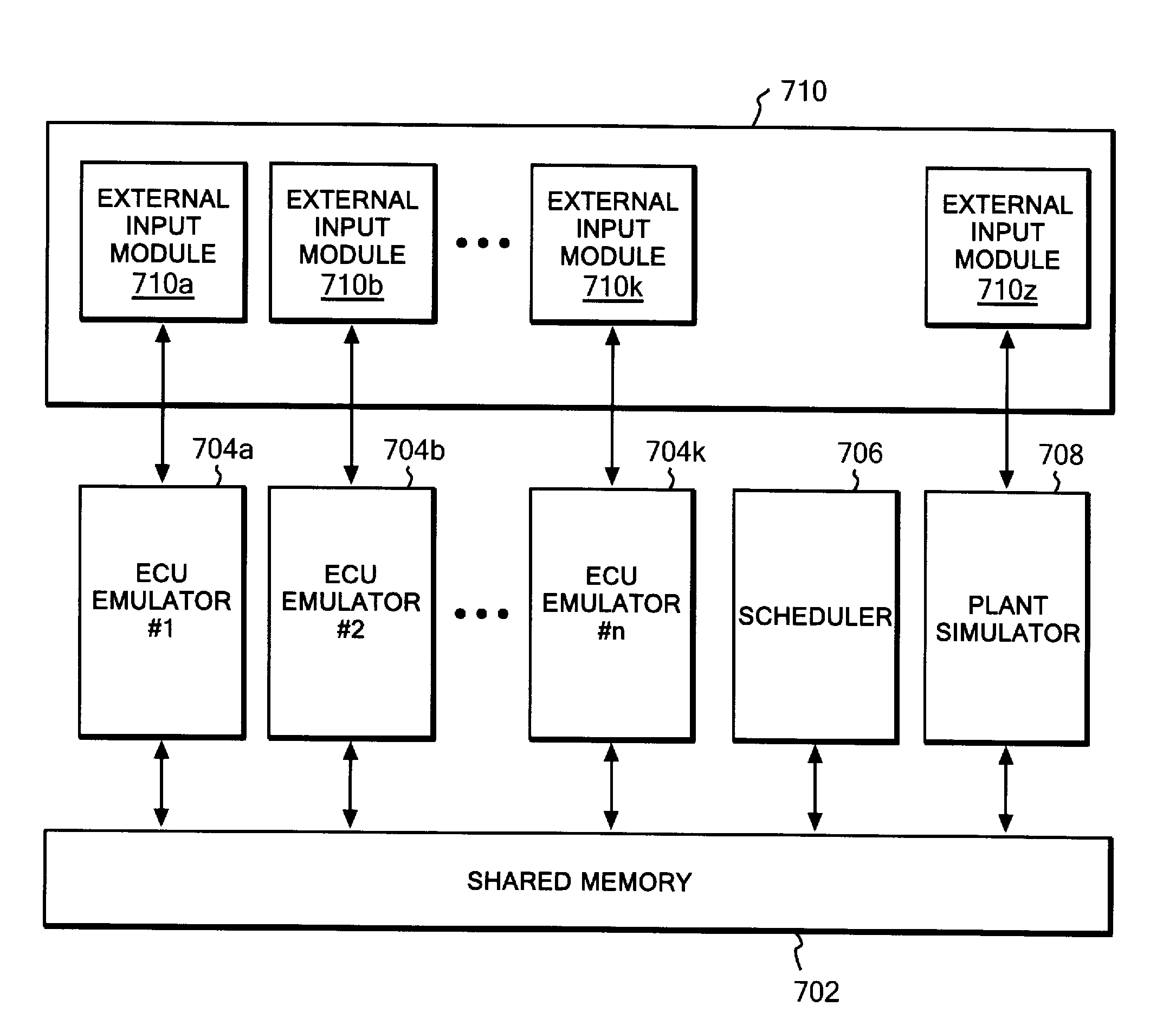
[0039]According to an embodiment of the present invention, a multi-CPU work station is preferably prepared. Moreover, a software emulator is prepared for each ECU. Generally, the software emulator of the ECU can be obtained from a manufacturer of the ECU.

[0040]The software emulator of each ECU is preferably interfaced with a predetermined layer in an operating system of the multi-CPU work station so as to run on the work station. Each of CPUs...


PUM


Abstract

A method, system, and computer readable article of manufacture for simulating a mechanism system controlled by a plurality of electronic control units operating at different clock rates. The simulation system includes a mechanism system simulator; a plurality of electronic control unit emulators for electronically emulating the respective plurality of electronic control units, each thereby receiving an input signal with a time and giving an output signal with a time; and a scheduler for receiving and storing the output signals with the times from the plurality of electronic control unit emulators, and for providing, in response to a change in the output signal coming from the electronic control unit emulator and having a relatively late time, the output signal with a time preceding the relatively late time to the mechanism system simulator.

Description

CROSS-REFERENCE TO RELATED APPLICATION[0001]This application claims priority under 35 U.S.C. §119 from Japanese Patent Application No. 2008-124053 filed on May 9, 2008, the entire contents of which are incorporated herein by reference.BACKGROUND OF THE INVENTION[0002]1. Field of the Invention[0003]The present invention relates to testing of an electronic control unit (ECU) which is used in an automobile, and more particularly relates to software-based testing of multiple ECUs.[0004]2. Description of Related Art[0005]The automobile, in its early stage, that is, in the early twentieth century, was composed of: an engine as a power source; and mechanical parts including a brake, an accelerator, a steering wheel, a transmission and a suspension. Almost no electrical mechanisms were used except for an ignition plug for the engine, and for headlights.[0006]However, around the 1970s, there arose the need to control the engine efficiently to deal with air pollution, oil crises, and the like...

Claims


Application Information

Patent Timeline
Patent Type & Authority Applications(United States)
IPC IPC(8): G06G7/64
CPCG05B17/02G05B2219/2637G05B2219/23455G05B2219/23446
Inventor KAJITANI, KOICHIKOMATSU, HIDEAKISHIMIZU, SHUICHI
Owner IBM CORP
Why Eureka
Try Eureka