Structurally integrated accessible floor system

a structurally integrated, accessible technology, applied in the direction of false floors, walls, ceilings, etc., can solve the problems of increasing labor and material costs, increasing the area of the exterior envelope, and labor premiums involved in having to locate and install the foregoing pedestal systems

Inactive Publication Date: 2009-11-19
ROEN ROGER C
View PDF52 Cites 31 Cited by
  • Summary
  • Abstract
  • Description
  • Claims
  • Application Information

AI Technical Summary

Benefits of technology

[0028]FIG. 13 is a partial cut-away plan view of the system of FIG. 9.

Problems solved by technology

There is a labor premium involved in having to locate and install the foregoing pedestal system.
The pedestals must be braced to meet seismic code, further increasing labor and material costs.
Moreover, the pedestals increase ceiling height requirements, and ultimately the height of the building, especially if the building has many stories, which increases the area of the exterior envelope, thereby increasing not only construction costs but also operating costs due to heat loss.
As users re-route electrical cables below the access floor, the pedestals may present an impediment in pulling cables to a new location.
The acoustical properties of this system are poor.
This low-profile design is less costly than the pedestal floor, but still impacts the cost of a traditionally designed floor in a building because it requires the use of a solid floor deck.
The problem of elevation changes between the existing conventional floor and accessible floor also remains.
There are also disadvantages to the low-profile floor compared to the pedestal floor.
The space below the low-profile sections is not deep enough to be used to supply air.
The resulting floor is not as stable, in either the horizontal or vertical dimension, as the pedestal access floor described above.
In general, the smaller distance between the solid floor deck and the surface of the floor sections decreases the flexibility of the low-profile floor.
In addition, the acoustical characteristics of both common types of elevated floors are typically very poor.
They tend to transmit noise to a degree that makes them impractical for use in many environments.
One disadvantage of this system is the height of the two layers of joists and the added height this imparts to a building.
The resulting weight and depth of the system is too great to be practical except where particularly heavy loads are imposed on the floor.
Also, the joists have to be welded at each intersection greatly increasing field labor costs.

Method used


Image

  • Structurally integrated accessible floor system
  • Structurally integrated accessible floor system
  • Structurally integrated accessible floor system

Examples


first embodiment

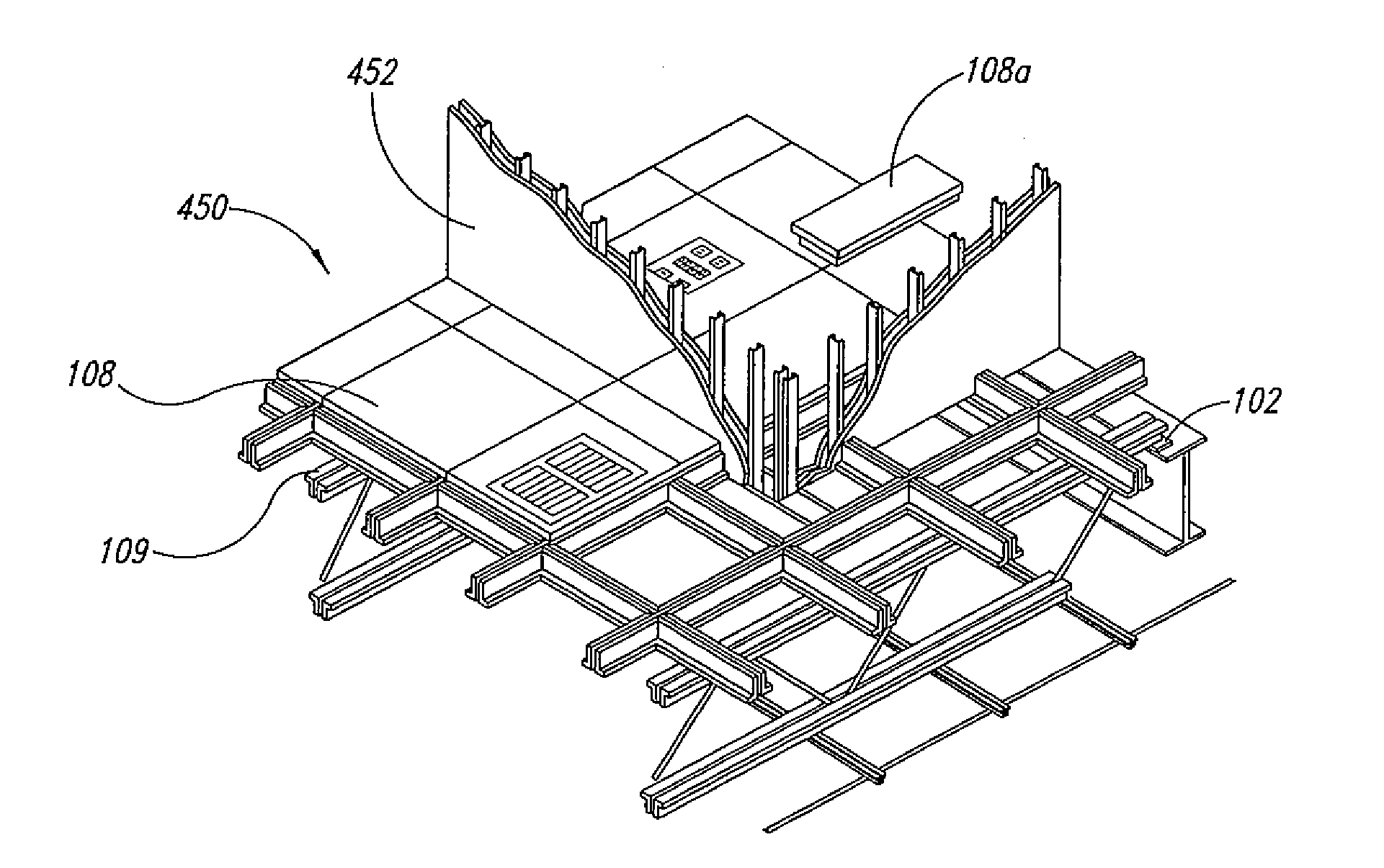
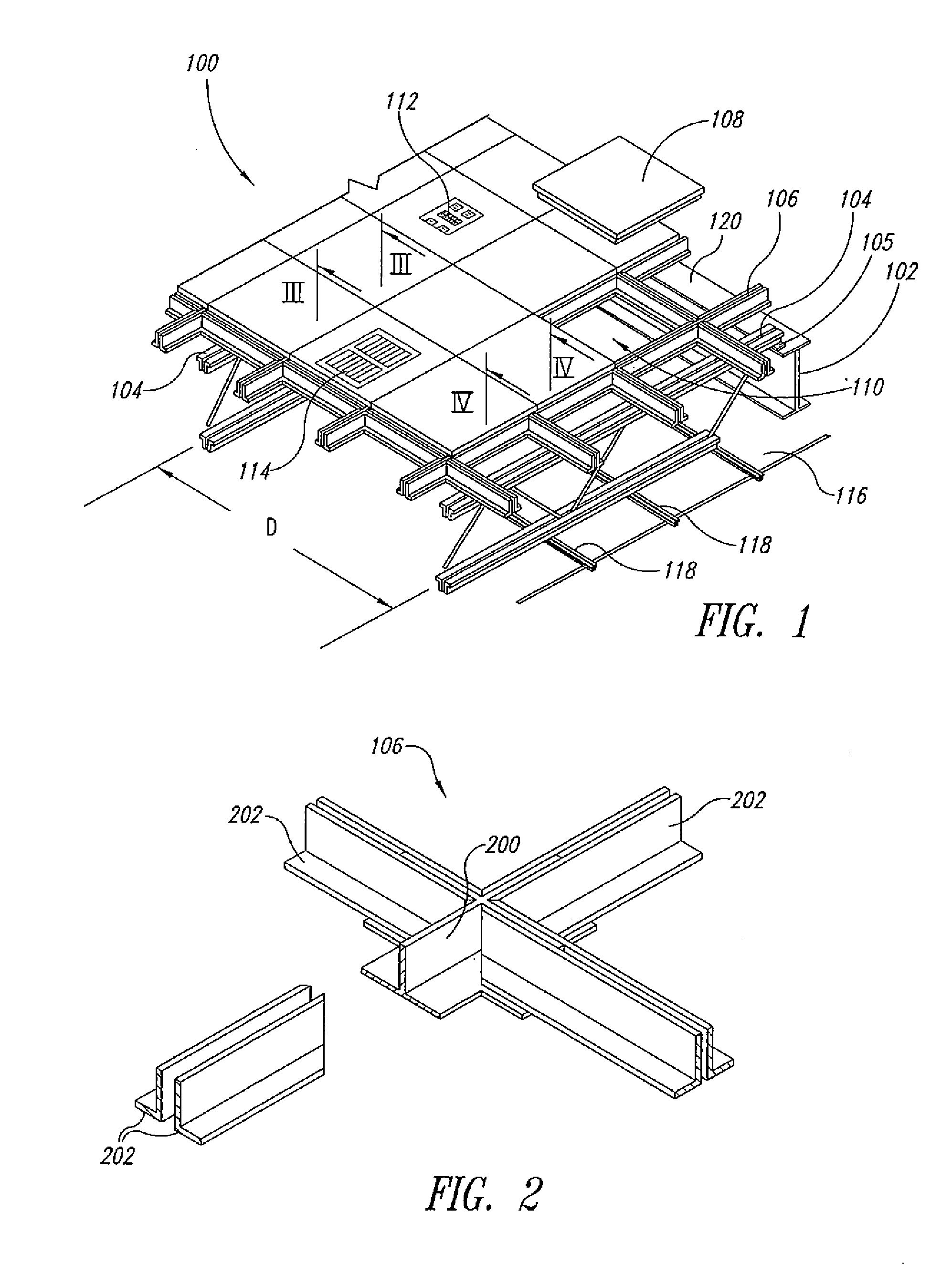
[0034] a structurally integrated accessible floor system, hereinafter referred to as the floor system, is designated generally as 100, and is shown isometrically in FIG. 1.

[0035]Primary framing members 102 are provided, which are integral parts of metal frame type buildings. Secondary framing members, such as joists 104 are connected to the primary framing members 102, typically by welding or riveting, although fasteners of various kinds, which are well known in the art, can be used. According to one embodiment of the invention, a structural support grid 106 is then formed, bearing on the secondary framing members 104. The grid 106 is configured to receive removable floor panels 108 in the openings 110 formed by the grid 106.

[0036]The grid 106 is configured to span across the secondary framing members 104 such that a plurality of floor panels 108 are supported by the grid between each secondary framing member 104, without the need for support by a secondary framing member for each f...

embodiment 460

[0059]FIG. 8 illustrates an alternative embodiment 460 of the invention in which structural support rails 462 are employed. The rails 462 span the secondary framing members 104 and support the removable floor panels 108 on two sides. The floor panels 108 of this embodiment are configured to have sufficient rigidity to span the space between the structural support rails 462 without the additional support of cross rails or bracing.

[0060]Another embodiment of the invention is described with reference to FIGS. 9-15. A floor system 900 is shown in FIG. 9 as part of a building structure. The system 900 includes a prefabricated floor section 902 having a first plurality of support rails 904. Each of the support rails 904 includes a pair of spaced-apart angle members running the full length of the section 902. Cross-support rails 906 are positioned at regular intervals between the support rails 904, each adjacent pair of support rails 904 and cross-support rails 906 forming an opening confi...


PUM


Abstract

A floor system for a building includes prefabricated grid sections attached to framing members of the building and a plurality of panels mounted to the grid to form a structurally integrated floor. The panels are removable to provide access to space below the floor that would otherwise be inaccessible in a conventional floor. A subfloor deck below the floor separates one building story from another and encloses the space between the floor and the deck, which can be used for temporary and permanent installations including, for example, pipes for water, laboratory gases, and compressed air, and power, telephone, and data cables; and as a plenum for HVAC. Either or both of the floor and the subfloor deck can be attached to the building frame to function as a diaphragm. The floor system replaces conventional permanent structural floors and raised accessible flooring systems.

Description

CROSS-REFERENCE TO RELATED APPLICATION[0001]This application is a continuation-in-part of U.S. patent application Ser. No. 10 / 410,934, filed Apr. 9, 2003, now pending, which application is a continuation-in-part of U.S. patent application Ser. No. 09 / 887,772, filed Jun. 21, 2001. Both applications are incorporated herein by reference in their entireties.BACKGROUND OF THE INVENTION[0002]1. Technical Field[0003]The present invention relates to floor structures in which space below the floor is accessible, and more specifically to an accessible floor structure that is structurally integrated with the associated building structure.[0004]2. Description of the Related Art[0005]The increase in the use of computers, communication devices, and other electronic hardware has placed new demands on building designers. Users desire a large number of outlets for access to electrical power and communication signals, and they need the ability to change the location of such outlets on a regular, some...

Claims


Application Information

Patent Timeline
Patent Type & Authority Applications(United States)
IPC IPC(8): E04F15/024E04B5/02E04C2/42
CPCE04B5/48E04B5/10
Inventor ROEN, ROGER C.
Owner ROEN ROGER C
Why Eureka
Try Eureka