Electromagnetic shifting device comprising a linear motor

a linear motor and shifting device technology, applied in the direction of mechanical actuated clutches, interengaging clutches, gearing, etc., can solve the problems of large shifting force, mechanical component wear phenomena, large mass that has to be moved, etc., to reduce the shifting force, improve the cold-running properties of the shifter pawl, and high dynamics

Inactive Publication Date: 2009-11-19
ZF FRIEDRICHSHAFEN AG
View PDF8 Cites 8 Cited by
  • Summary
  • Abstract
  • Description
  • Claims
  • Application Information

AI Technical Summary

Benefits of technology

[0009]During a shift operation in a shift transmission the positions of the shifter pawls are detected. According to the invention, the actual position of the shifter pawl is recognized by the linear motor directly on the shifter pawl, for example by virtue of the change of inductivity. To reduce the shifting forces at low temperatures, the linear motor can be actuated so that it serves as a heat source. In this way, the transmission oil, at least locally in the area of the shifting device, is warmed to operating temperature whereby the cold-running properties of the shifter pawl are improved. Furthermore, linear motors are characterized by high dynamics so that the shifter pawl can be actuated and a shift carried out rapidly. A linear motor can be used to actuate the shifter pawl in any shift transmission, for example in claw-type or synchronous transmissions. In addition, a different design form of the linear motor is conceivable, for example as a synchronous motor, an asynchronous motor, a direct-current motor or a cross-flow motor.
[0010]Since the shifter pawl is actuated by the shifting device described, no actuation elements are needed between the toothed gear wheels and these can therefore be arranged closer to one another, so improving upon the disadvantages of known shifting devices as regards component arrangement, the use of available space and the possibility of access to the shift elements.

Problems solved by technology

The disadvantages of such shift mechanisms are wear phenomena of the mechanical components and the large masses that have to be moved during the shift operation.
A disadvantage of the shifting devices described in the prior art is that at low temperatures large shifting forces have to be applied, since the oil on the shifter pawl becomes very viscous at low temperatures.

Method used


Image

  • Electromagnetic shifting device comprising a linear motor
  • Electromagnetic shifting device comprising a linear motor
  • Electromagnetic shifting device comprising a linear motor

Examples


Embodiment Construction

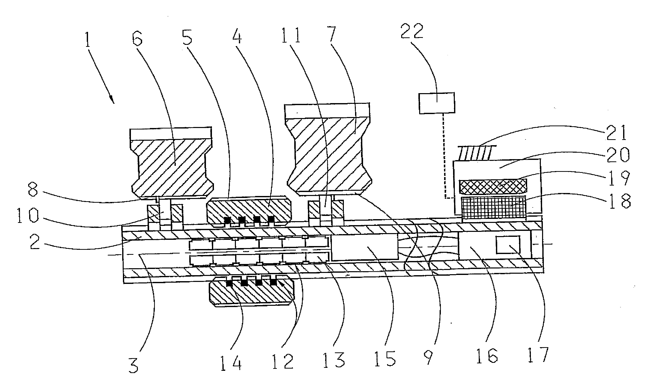
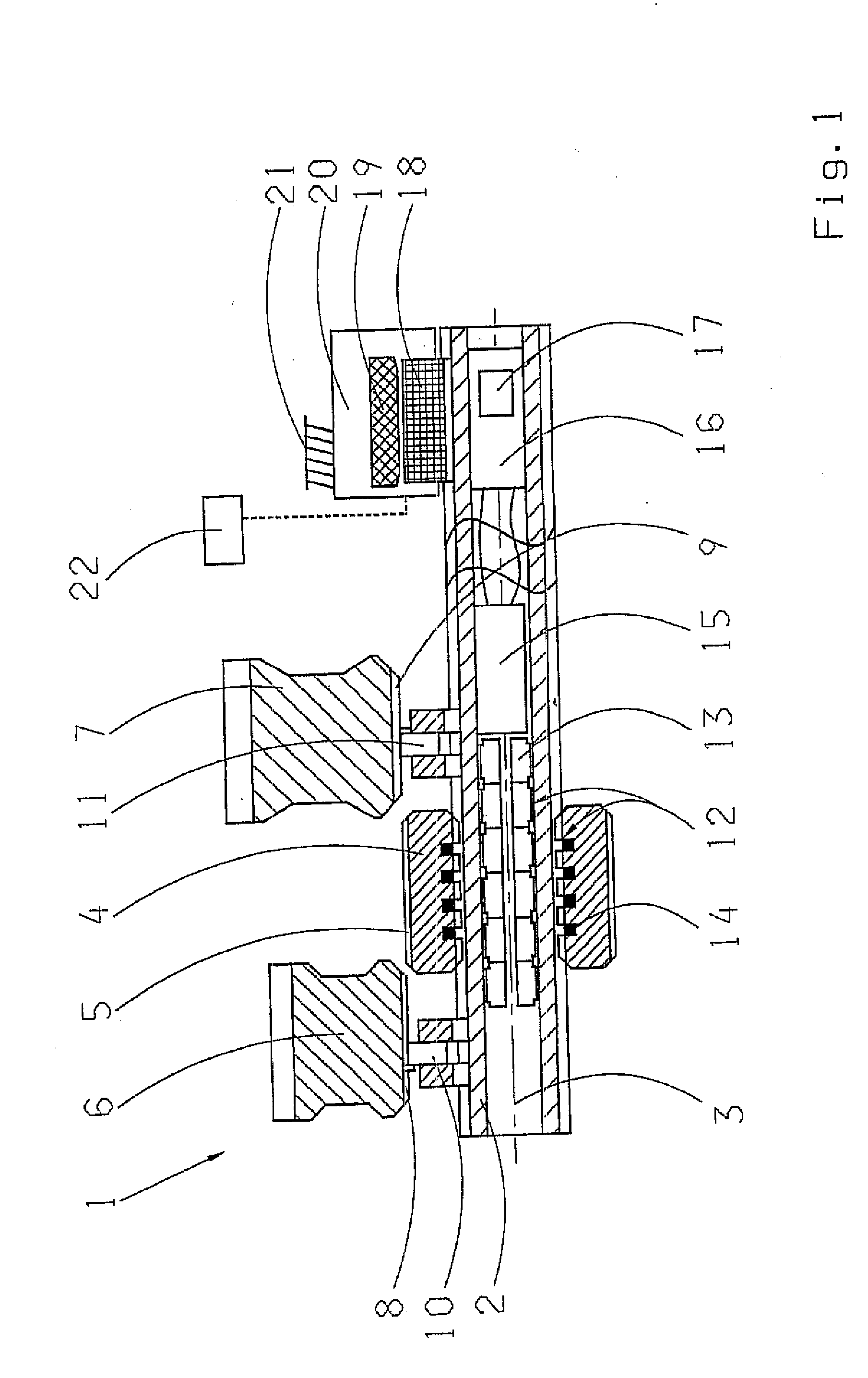
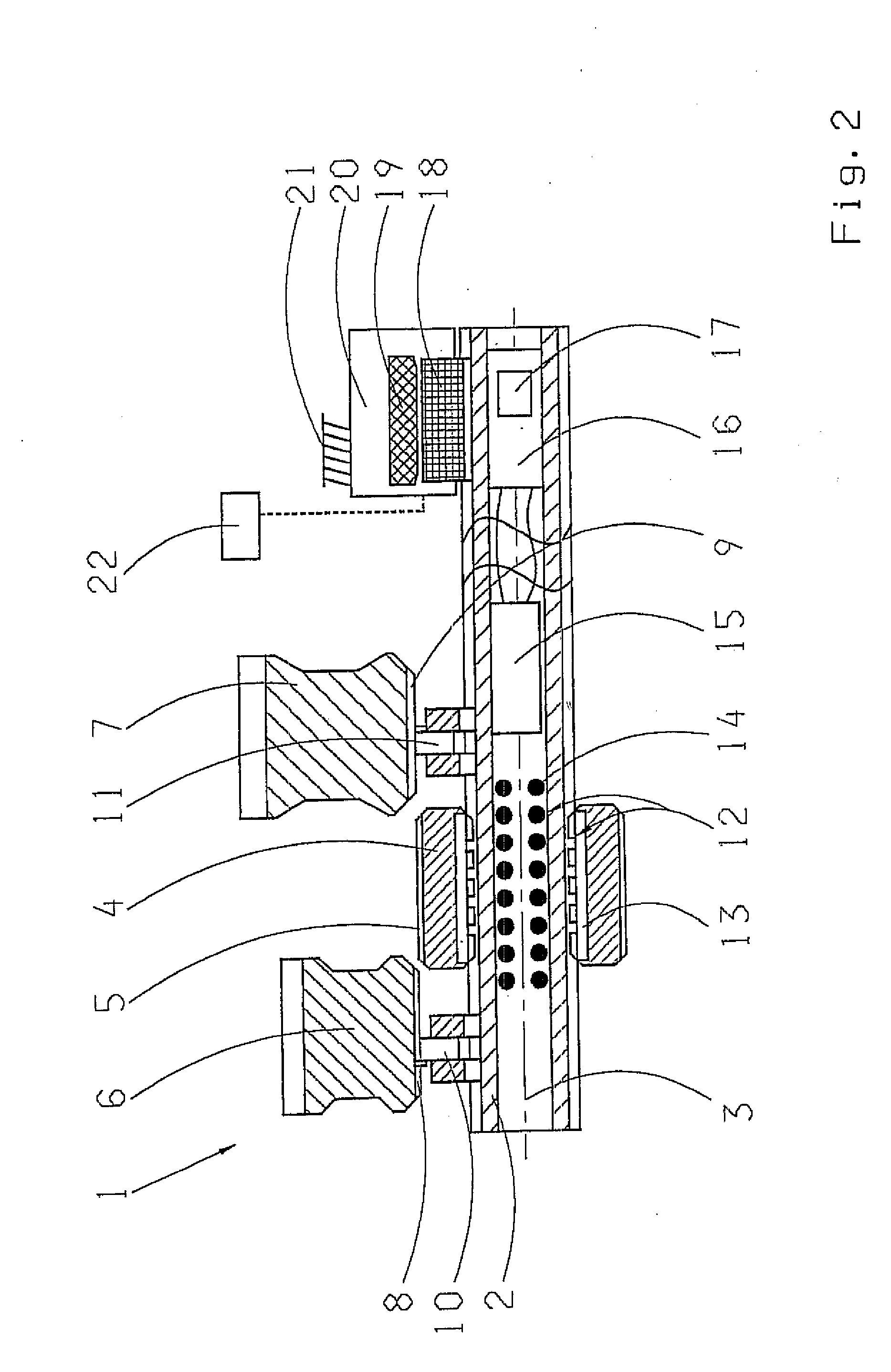
[0014]FIG. 1 shows a section of a transmission 1. A first toothed gear wheel 6 and a second toothed gearwheel 7 are held by bearings 10 and 11 axially fixed, but able to rotate on a transmission shaft 2. The toothed gear wheels 6 and 7 each have inner teeth 8 and 9. A shifter pawl 4 is arranged rotationally fixed, but able to move axially on the transmission shaft 2, along an axis 3 of the transmission shaft 2. A primary portion 14 of a linear motor 12 is arranged in the shifter pawl 4 and a secondary portion 13 of the linear motor 12 is arranged in the transmission shaft 2, which is made as a hollow shaft. The linear motor 12 has a control unit 15 which is also accommodated in the transmission shaft 2. The control unit 15 could likewise be arranged outside or on the transmission shaft 2 (not shown here). A generator unit 20 is attached on a transmission housing 21. The generator unit 20 consists of a magnet 19, arranged in a fixed position and a rotationally fixed coil 18. Energy i...


PUM


Abstract

An electromagnetic shifting device for a transmission (1) with an electronic control unit (22) and toothed gear wheels (6, 7), which are mounted to rotate on a transmission shaft (2) about an axis (3). To implement a gear stage, the toothed gear wheels can be connected in a rotationally fixed manner to the transmission shaft by moving a shifter pawl (4) axially along the axis. The shifter pawl is moved axially along the axis by a linear motor (12).

Description

[0001]This application is a national stage completion of PCT / EP2007 / 051427 filed Feb. 14, 2007, which claims priority from German Application Serial No. 10 2006 009 606.1 filed Mar. 2, 2006.FIELD OF THE INVENTION[0002]The invention concerns an electromagnetic shifting device for a vehicle transmission.BACKGROUND OF THE INVENTION[0003]In the prior art shift transmissions are described, in which gears are engaged by way of sliding sleeves. Such a sliding sleeve is connected to a shifting device which can comprise a shift fork with slide blocks and a shift rod. The sliding sleeve is connected in a rotationally fixed manner to the transmission shaft by the shifting device. Toothed gearwheels mounted to rotate on the transmission shaft, which mesh with other toothed gear wheels attached solidly on the countershaft. When the sliding sleeve is axially displaced by the shifting device in the direction toward the toothed gear wheel mounted to rotate on the transmission shaft, by virtue of in...

Claims


Application Information

Patent Timeline
Patent Type & Authority Applications(United States)
IPC IPC(8): F16H59/04
CPCF16D11/14F16D28/00F16D2011/004Y10T74/2003F16H2063/3053Y10T74/19465F16H63/304
Inventor MULLER, BERND
Owner ZF FRIEDRICHSHAFEN AG
Why Eureka
Try Eureka