

Motor with an electromagnetic brake
a technology of electromagnetic brake and motor, which is applied in the direction of mechanical energy handling, dynamo-electric machines, supports/encloses/casings, etc., can solve the problems of ineffective reduction of the influence of the leakage magnetic flux on the magnetic sensor, the inability to effectively flow the leakage magnetic flux from the internal fan to the heat shielding plate, and the inability to achieve the effect of reducing the density of the leakage magnetic flux, reducing the density of the leakage magneti
- Summary
- Abstract
- Description
- Claims
- Application Information
AI Technical Summary
Benefits of technology
Problems solved by technology
Method used
Image

Examples
Embodiment Construction
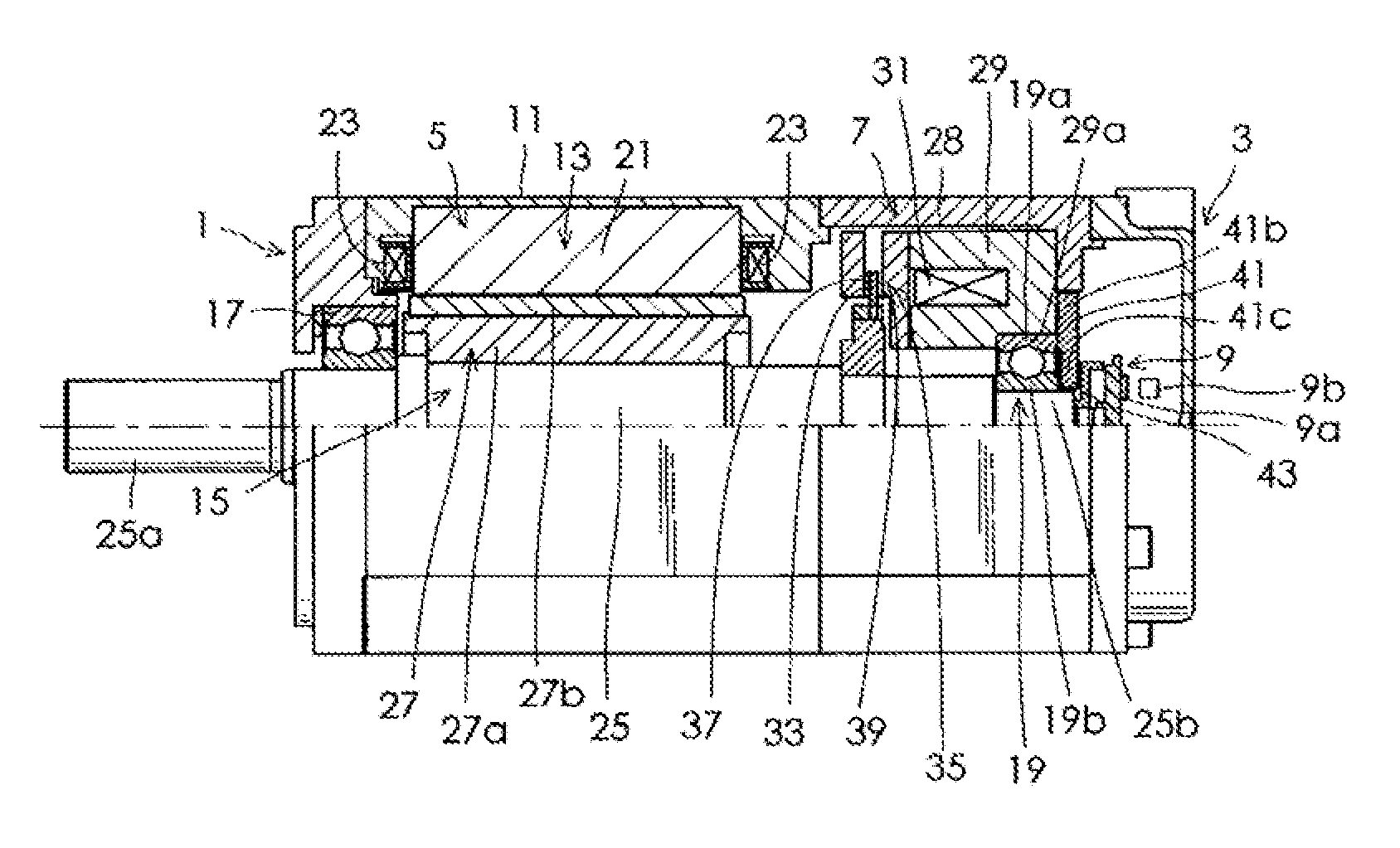
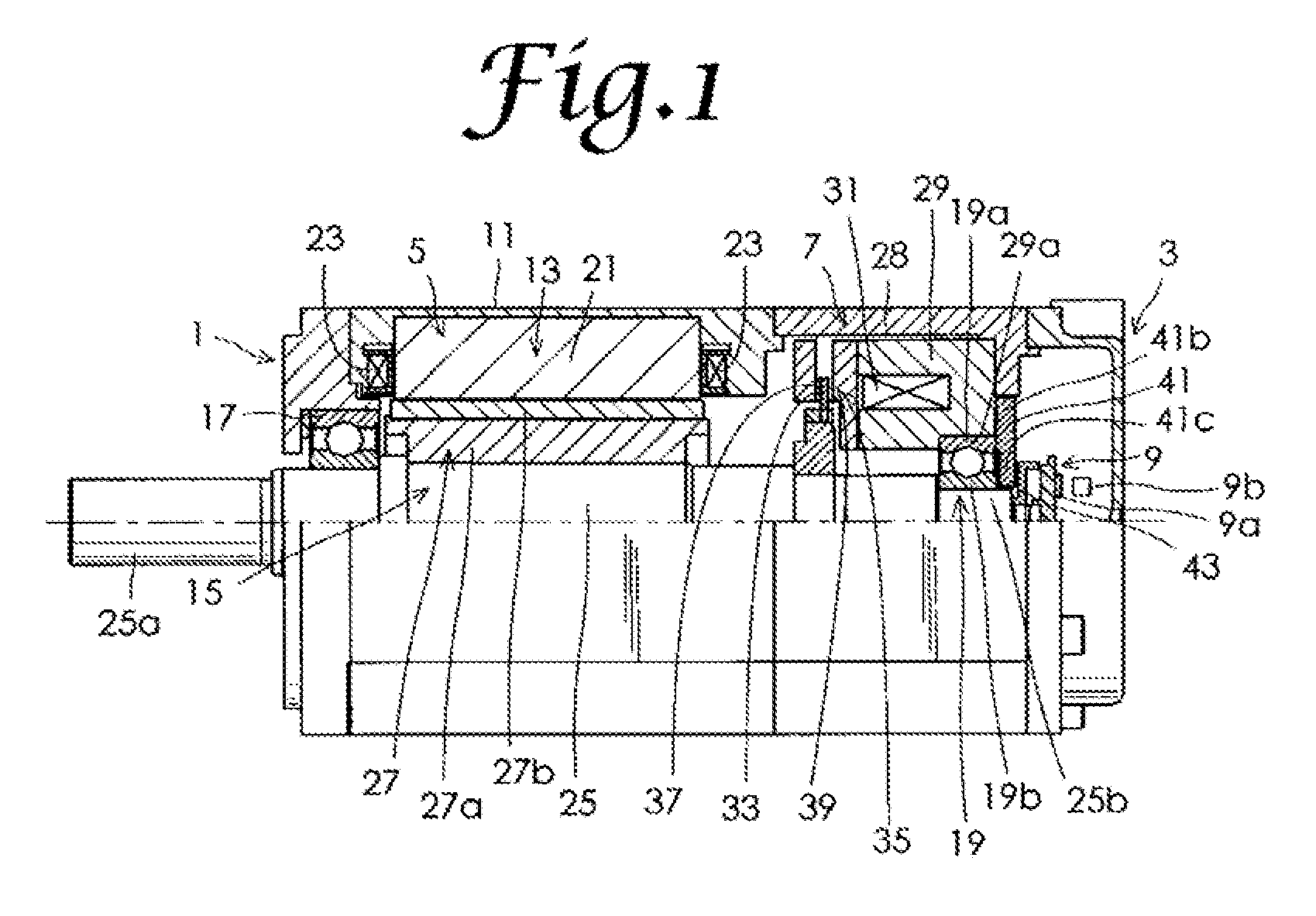
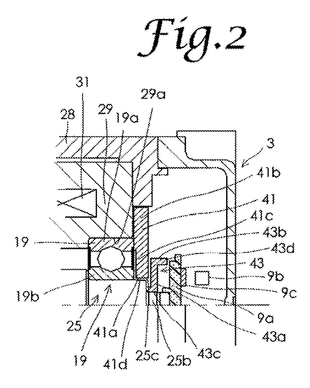
[0028]Embodiments of the present invention will be described below in detail, with reference to drawings. FIG. 1 sows a cutaway half-portion of a motor with an electromagnetic brake in a first embodiment of the present invention. FIG. 2 is a partially magnified view of FIG. 1. As shown in FIG. 1, the motor with an electromagnetic brake in this embodiment includes an end bracket 1, a sensor cover 3, a motor portion 5, an electromagnetic brake 7, and a magnetic sensor 9 that constitutes a rotation position detector. The motor portion 5 includes a cylindrical housing 11, a motor stator 13, a motor rotor 15, and a first hall bearing 17 and a second ball bearing 19 that respectively constitute first and second bearings. Though balls of the first ball bearing 17 and the second ball bearing 19 are drawn as polygons for the purpose of illustration, the balls are actually spherical. The motor stator 13 is fixed to inside the housing 11, and includes a stator core 21 and a plurality of windin...
PUM
 Abstract
Description
Claims
Application Information