Motor Control Device, Control Method, and Control Program

a control device and motor technology, applied in the field of motors, can solve the problems of affecting the accuracy of conventional estimation methods, affecting the accuracy of accurate temperature estimation, and the increase of heat produced by the magnet itself, and achieve the effect of not increasing the computational load of the computer

Inactive Publication Date: 2009-11-19
TOYOTA JIDOSHA KK
View PDF6 Cites 39 Cited by
  • Summary
  • Abstract
  • Description
  • Claims
  • Application Information

AI Technical Summary

Benefits of technology

[0018]Advantageously, the present invention calculates the temperature of the rotor magnet based on a plurality of parameters, so that the rotor magnet temperature can be estimated precisely and the motor can be controlled properly.
[0019]Also, the present invention calculates the temperature of the rotor magnet using the predetermined heat production ratio and the heat resistance ratio and also using the temperature of the easily measurable part of the motor, so that the rotor magnet temperature can be calculated without increasing the computational load of the computer.

Problems solved by technology

As the motor is controlled in a more complicated way to attain higher output, the rotor magnet itself produces an increased amount of heat, which hampers a sufficiently precise estimation of the temperature using conventional estimation methods.
This is especially true with the motors used in hybrid vehicles in which the driving state changes momently, because the temperature of the rotor magnet might include a predetermined error if the temperature is estimated only from the motor cooling oil.

Method used


Image

  • Motor Control Device, Control Method, and Control Program
  • Motor Control Device, Control Method, and Control Program
  • Motor Control Device, Control Method, and Control Program

Examples


Embodiment Construction

[0027]An embodiment of the present invention (referred to as “the embodiment” hereinafter) will be described below with reference to the attached drawings.

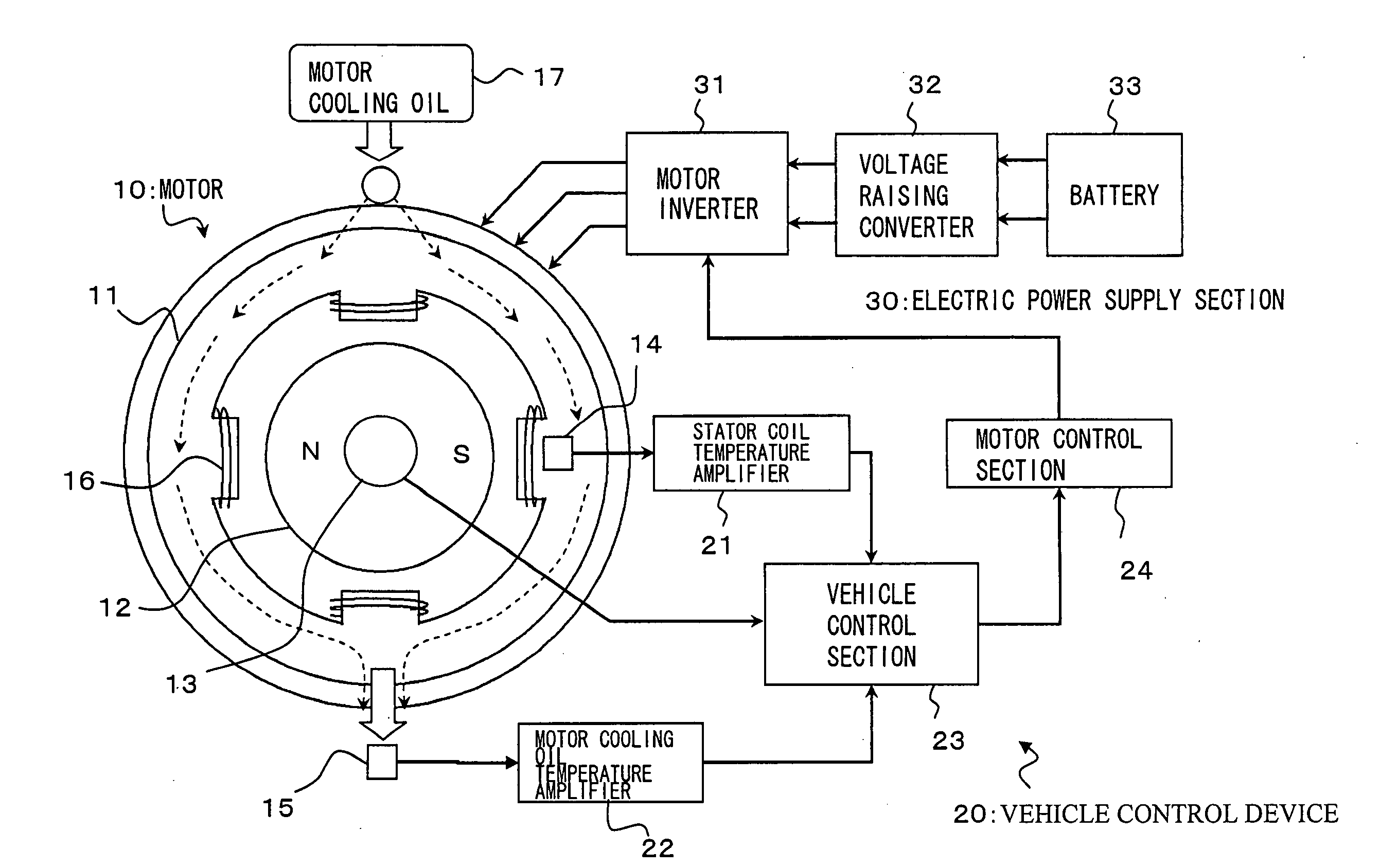
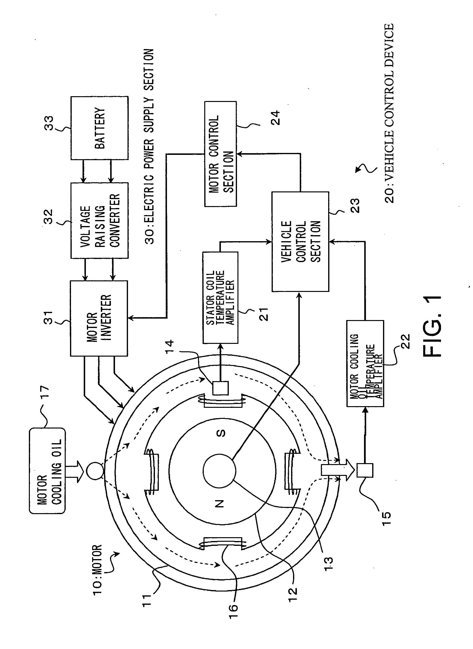
[0028]FIG. 1 shows a motor control device 20 for controlling a motor 10. The motor 10 includes a rotor 12 having a permanent magnet, a reservoir 13 provided in the rotor 12, a stator 11 arranged on the outer side of the rotor 12 and having a stator coil 16, and a temperature sensor 14 for detecting the temperature of the stator coil 16.

[0029]A motor control device 20 for controlling the motor 10 includes a stator coil temperature amplifier 21, a motor cooling oil temperature amplifier 22, a vehicle control section 23, and a motor control section 24. Further, a power supply section 30 for supplying electric power to the motor 10 includes a battery 33, a voltage raising converter 32 for raising a voltage of the battery, and a motor inverter 31 for supplying electric power to the motor 10 in response to an instruction from the motor ...


PUM


Abstract

The temperature of a stator coil is measured by a temperature sensor (14), amplified by a stator coil temperature amplifier (21), and transmitted to a vehicle control section (23). Further, motor cooling oil (17) for cooling the outer periphery of the stator cools the stator coil (16) along an end coil section of the stator coil (16). The temperature of the motor cooling oil raised by the stator coil (16) is measured by a temperature sensor (15) and transmitted also to the vehicle control section (23) via a motor cooling oil temperature amplifier (22). The vehicle control section (23) estimates the temperature of a rotor magnet based on a thermal model (relationship between temperature, a heat production amount, and heat resistance) of the motor cooling oil, the stator coil, and the rotor magnet by using the motor cooling oil temperature and the stator coil temperature as input values and sends a control instruction to a motor control section (24).

Description

BACKGROUND OF INVENTION[0001]1. Field of the Invention[0002]The present invention relates to a motor control device for operating a motor having a stator with a stator coil concentrically arranged on the outer side of a rotor having a permanent magnet, the motor control device including magnet temperature estimating means for estimating a temperature of the permanent magnet, and control means for controlling the motor based on the estimated magnet temperature. The present invention also relates to a control method and a control program of such motors.[0003]2. Description of the Related Art[0004]Recently, there has been increasing interest in hybrid vehicles, electric vehicles, and vehicles powered by fuel cells, and various attempts have been made to improve the driving performance of such vehicles to go beyond conventional vehicles driven by internal combustion engines. For example, in hybrid vehicles, attempts to increase the energy efficiency of vehicles to improve the driving pe...

Claims


Application Information

Patent Timeline
Patent Type & Authority Applications(United States)
IPC IPC(8): H02P23/14H02P27/08H02P21/14H02P27/06
CPCG01K7/42H02P29/0044H02P23/14G01K2205/00H02P29/60
Inventor MIURA, TETSUYA
Owner TOYOTA JIDOSHA KK
Why Eureka
Try Eureka