Inkjet printhead and a method of inkjet printing

a technology of inkjet printing and printhead, which is applied in the field of inkjet printhead and inkjet printing method, can solve the problems of not always completely reliable control technique and complicated use of control technique, and achieve the effect of reducing the number of wiring connections and high maximum firing ra

Inactive Publication Date: 2009-11-19
TELECOM ITALIA SPA +1
View PDF7 Cites 18 Cited by
  • Summary
  • Abstract
  • Description
  • Claims
  • Application Information

AI Technical Summary

Benefits of technology

[0021]The Applicant has realized that by sending a single firing signal to all the matrices, it is possible to increase the number of firing cells which are simultaneously activated at each firing cycle (i.e., the time between successive firings of different resistors), so that a proper arrangement of the ink dots on the printed medium is achieved.
[0022]Since the firing cells of each matrix are energized at the same time, no change of the position of the printhead with respect to the recording medium occur during activation of the different matrices, thereby assuring a correct arrangement of the ink spots on the recording medium.
[0023]The Applicant has found that by employing two separated memory registers, a first memory register used to store printing data for the current printing step and a second memory register used to store printing data for the next printing step, it is possible to maintain a high maximum firing rate (i.e. the frequency at which each resistor can be successively energized, also referred to as the “working frequency” of the printhead), and to reduce the wiring connections necessary to address the firing cells for a correct working of the printhead. Loading of the second memory register can occur in a least partial overlap of the current printing step, preferably during the current printing step.

Problems solved by technology

The Applicant has verified that, in order to obtain a precise printing by means of such a printhead, a complicated and not always completely reliable control technique has to be employed, since the firing signals sent to the matrices need to be synchronized with the movement of the carriage which supports the printhead.

Method used


Image

  • Inkjet printhead and a method of inkjet printing
  • Inkjet printhead and a method of inkjet printing
  • Inkjet printhead and a method of inkjet printing

Examples


first embodiment

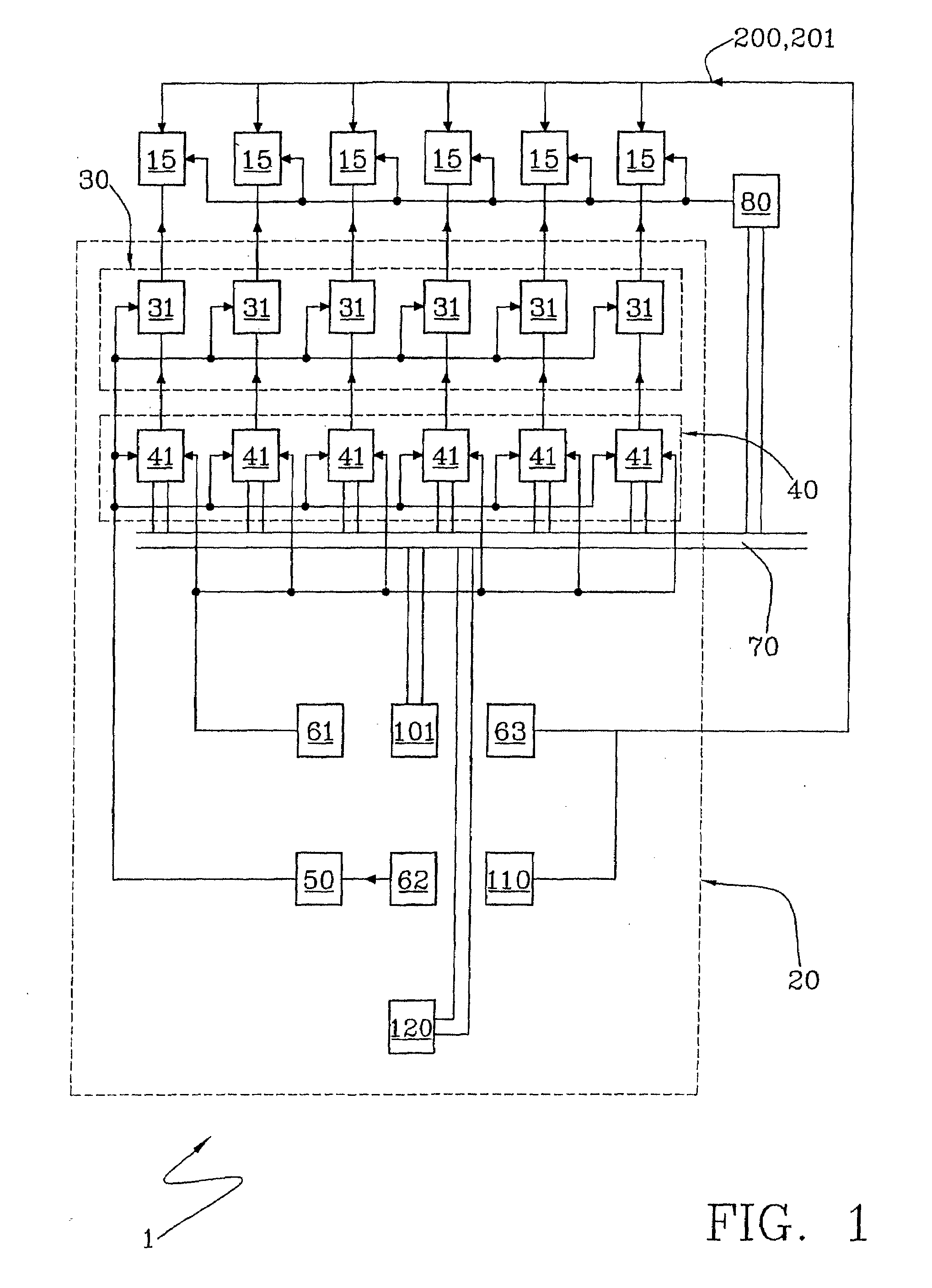
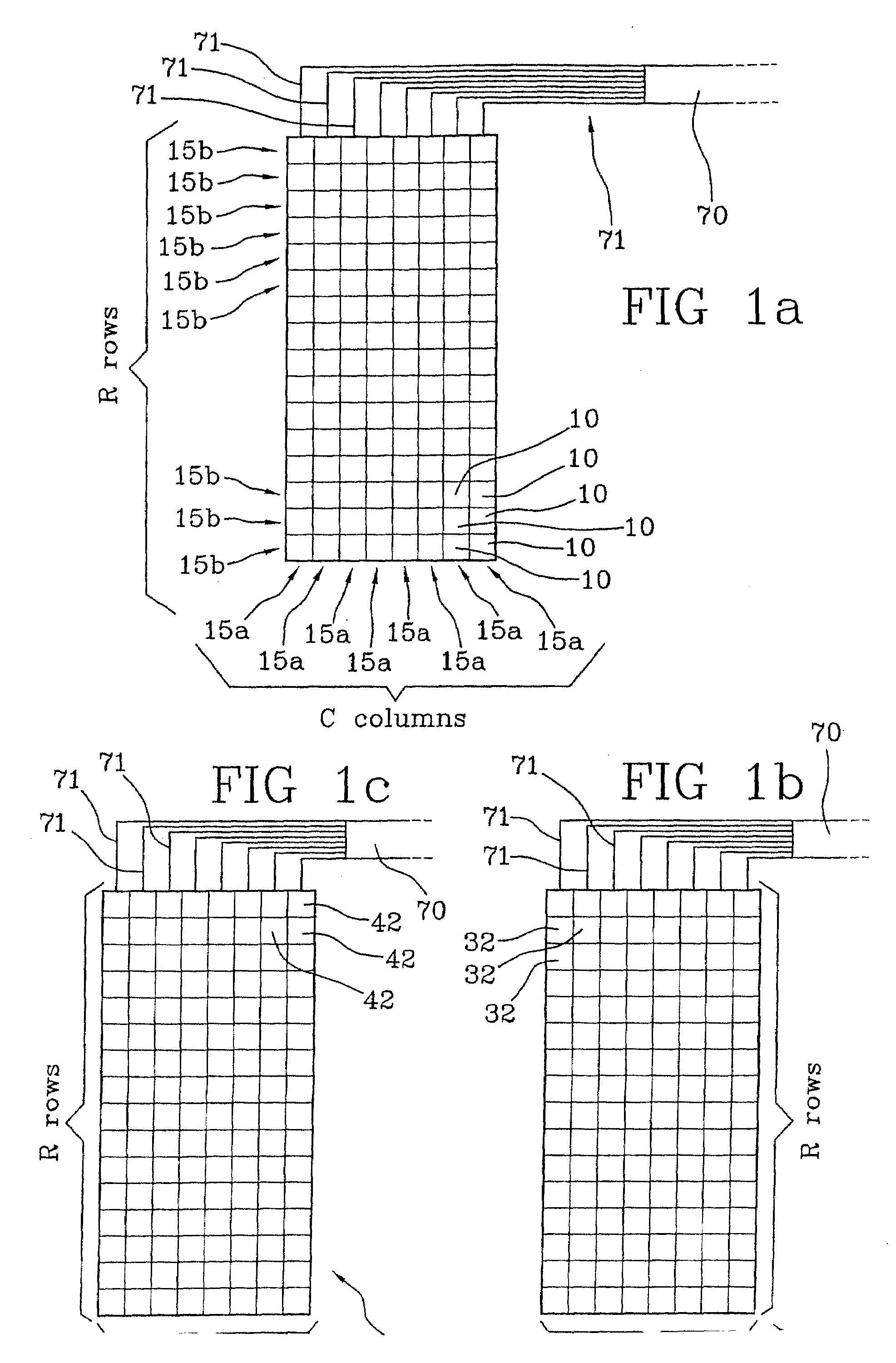
[0133] the number R of rows of each matrix 15 is equal or smaller than the number of channels 71 of the bus connection 70. FIG. 5a illustrates an embodiment in which each row 15b is associated with a corresponding channel 71, so that when a preset row 15b is to be selected, a selection signal (for example, a “1” pulse) is sent by the addressing block 101 through the channel 71 associated with such preset row.

[0134]In practice, in order to select a row of a matrix 15 which has to be enabled to eject ink during a certain printing operation, a single signal (i.e. the aforementioned selection signal) is transmitted from the addressing block 101 to such a row, so that that row is activated in the printing operation.

second embodiment

[0135] the number R of rows of the matrices 15 is larger than the number of channels 71 (FIG. 5b). In such a case, the available channels are not sufficient for address in a one-to-one correspondence all the rows 15b. The control circuit 20 comprises a decoding unit 80, operatively interposed between the bus connection 70 and the matrices 15 for associating each row 15b of such matrices 15 with a combination of channels 71, e.g., a combination of two channels is associated to a row 15a.

[0136]Thus, each single channel 71 can be connected to more than one row 15b.

[0137]By way of example, in case a bus having eight channels is employed to address sixteen rows, FIG. 4a shows a table in which each of the rows 15b of the matrices 15 is identified by a combination of channels 71. For example, row 1 corresponds to a combination of channels 7 and 6.

[0138]If the digital electronic control uses negative, bipolar logic, a positive voltage represents logic “0”. Given the value “0” to the selec...


PUM


Abstract

An inkjet printhead comprising a plurality of firing cells, each adapted to generate ink droplet, said firing cells being arranged to form a plurality of matrices; a control circuit for selectively activating said firing cells; said control circuit comprising: a first memory register for storing main printing data defining which firing cells have to be activated in a first printing operation; a second memory register for storing auxiliary printing data defining which firing cells have to be activated in a second printing operation; a processing unit operatively associated with said first and second memory registers for transferring said auxiliary printing data into said first memory register, thereby defining which firing cells have to be activated in said second printing operation; a firing unit for sending to said matrices a single firing signal for each printing operation. Also disclosed is a method of inkjet printing.

Description

CROSS-REFERENCE TO RELATED APPLICATIONS[0001]This application is a National Stage Application of PCT / EP2005 / 013992, filed Dec. 23, 2005, which designates the United States.BACKGROUND OF THE INVENTION[0002]The present invention relates to an inkjet printhead and a method of inkjet printing. In particular, the invention relates to a thermal ink jet printhead and a method of thermal ink jet printing.[0003]Inkjet printers print dots by ejecting very small drops of ink onto a print medium, generally paper, and typically include a movable carriage that supports one or more printheads each having ink ejecting nozzles (or orifices). The carriage traverses over the surface of the print medium, and the nozzles are controlled to eject droplets of ink at appropriate times pursuant to commands from a microcomputer or other controller, wherein the timing of the ejection of the ink drops is intended to correspond to the pattern of pixels of the image being printed.[0004]The printheads of thermal i...

Claims


Application Information

Patent Timeline
Patent Type & Authority Applications(United States)
IPC IPC(8): B41J29/38
CPCB41J2/04528B41J2/04541G06K15/102B41J2/0458B41J2/04596B41J2/04543
Inventor CERUTTI, WALTER
Owner TELECOM ITALIA SPA
Why Eureka
Try Eureka