Mirror Assembly with Recessed Mirror

a mirror assembly and mirror technology, applied in the field of mems devices (microelectric mechanical systems), can solve the problems of limiting the mirror to the same thickness as the hinge, and the mirror control may not be optimized for an application, and achieve the effects of low cost, thinner mirror, and higher resonant frequency

Active Publication Date: 2009-11-19
TEXAS INSTR INC
View PDF8 Cites 19 Cited by
  • Summary
  • Abstract
  • Description
  • Claims
  • Application Information

AI Technical Summary

Benefits of technology

[0007]Advantages of preferred embodiments of the present invention include providing a low cost method of manufacturing a mirror assembly. A further advantage is that a mirror thinner than the hinge / support structure may be used, allowing thicker torsional hinge regions for a relatively thinner mirror. The combined structure may allow a higher resonant frequency. A mirror with a higher resonant frequency may enable better mirror control and quicker mirror reaction time.

Problems solved by technology

However, manufacturing MEMS mirrors and hinge structures from one substrate may limit the mirror to the same thickness as the hinge.
Therefore, mirror control may not be optimized for an application.

Method used


Image

  • Mirror Assembly with Recessed Mirror
  • Mirror Assembly with Recessed Mirror
  • Mirror Assembly with Recessed Mirror

Examples


Embodiment Construction

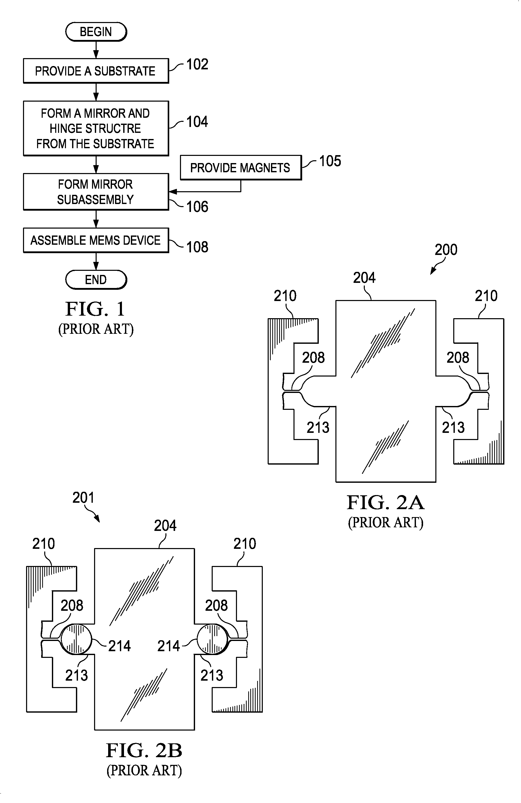
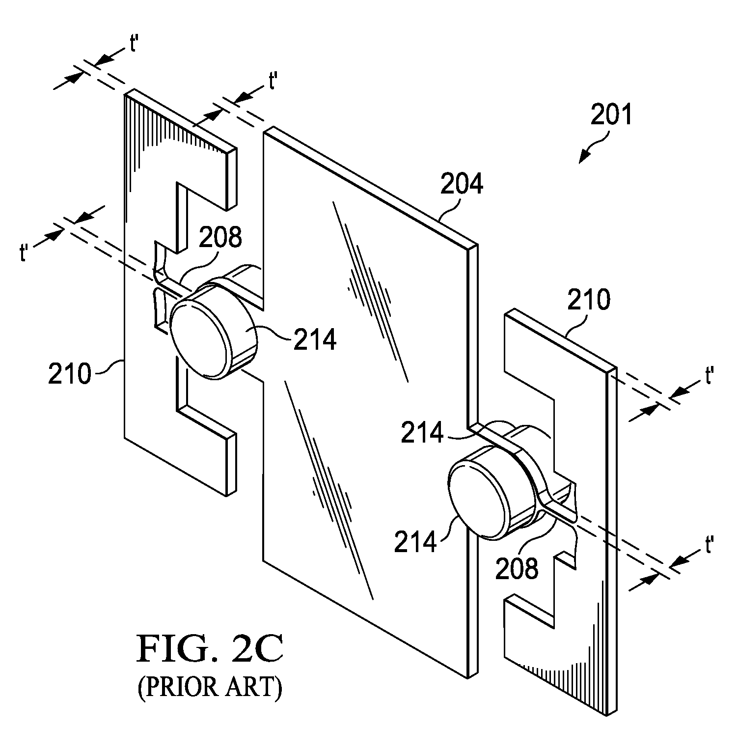
[0016]The making and using of the presently preferred embodiments are discussed in detail below. It should be appreciated, however, that an illustrative embodiment provides many applicable inventive concepts that can be embodied in a wide variety of specific contexts. The specific embodiments discussed are merely illustrative of specific ways to make and use the invention, and do not limit the scope of the invention.

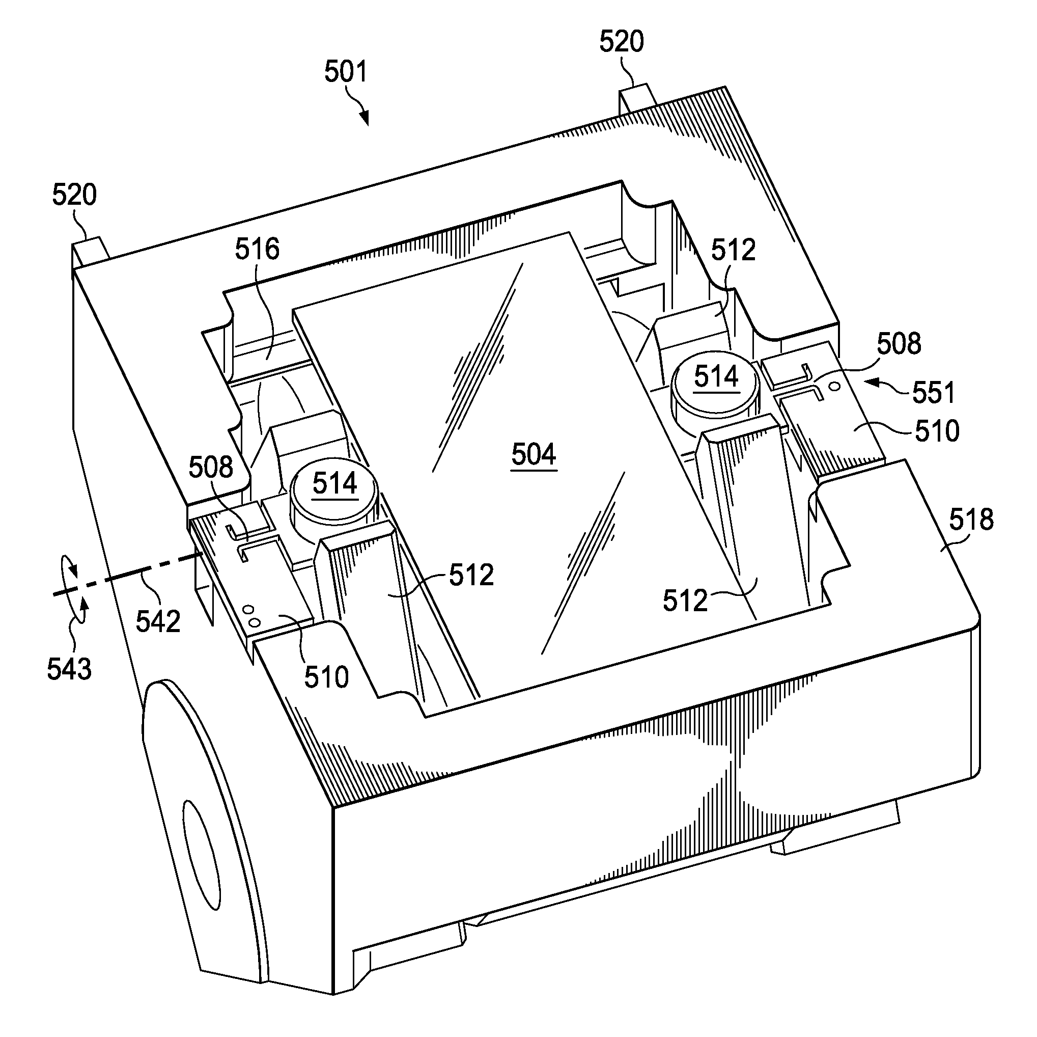
[0017]The present invention will be described with respect to illustrative embodiments in a specific context, namely a MEMS pointing mirror. A MEMS pointing mirror may be used in applications such as, for example, fiber optic technologies. The invention may also be applied, however, to other MEMS mirror devices and applications, including applications which require the MEMS mirror to operate at resonant frequencies.

[0018]Pointing mirrors may often be operated far from resonant frequency. Operation of a mirror at the resonant frequency of an oscillating mirror may cause i...


PUM

PropertyMeasurementUnit
thicknessaaaaaaaaaa
flatnessaaaaaaaaaa
thicknessaaaaaaaaaa

Abstract

A mirror device and a method for manufacturing the mirror device are presented. The mirror device includes a mirror formed from a first substrate and a hinge/support structure formed from a second substrate. The hinge/support structure includes a recessed region and a torsional hinge region. The mirror is coupled to the hinge/support structure at the recessed region. Further, a driver system is employed to cause the mirror to pivot about the torsional hinge region.

Description

TECHNICAL FIELD[0001]The present invention relates generally to MEMS devices (micro-electric mechanical systems) and more specifically to a MEMS structure and a method of manufacturing a MEMS mirror assembly with a recessed mirror.BACKGROUND[0002]Micro-mechanical devices or micro-electromechanical systems (MEMS) are micron-scale devices, often with moving parts, that may be fabricated using traditional semiconductor processes such as optical lithography, metal sputtering, oxide deposition, and plasma etching, which have been developed for the fabrication of integrated circuits.[0003]Micromirrors, such as the DMD™ micromirror array from Texas Instruments, are a type of micro-mechanical device. Other types of micro-mechanical devices include accelerometers, pressure and flow sensors, gears, and motors. Pivoting or oscillating torsional hinged mirrors provide very effective and inexpensive replacements for spinning polygon shaped mirrors in printers and some types of displays. Further,...

Claims


Application Information

Patent Timeline
Patent Type & Authority Applications(United States)
IPC IPC(8): G02B26/08B29D11/00
CPCB29D11/00596G02B26/085Y10T29/49007Y10T29/49126Y10T29/49124Y10T29/49155Y10T29/49131Y10T29/49204Y10T29/4913
Inventor ORCUTT, JOHN W.
Owner TEXAS INSTR INC
Why Eureka
Try Eureka