Control circuit and method for a flyback converter

a control circuit and converter technology, applied in the field of flyback converters, can solve the problems of switching loss and reduce the efficiency of the converter, and achieve the effect of reducing the switching loss

Active Publication Date: 2009-11-19
RICHTEK TECH
View PDF10 Cites 54 Cited by
  • Summary
  • Abstract
  • Description
  • Claims
  • Application Information

AI Technical Summary

Benefits of technology

[0006]An object of the present invention is to provide a control circuit and method for a flyback converter to comp

Problems solved by technology

However, when a switching power converter is under light load

Method used


Image

  • Control circuit and method for a flyback converter
  • Control circuit and method for a flyback converter
  • Control circuit and method for a flyback converter

Examples


first embodiment

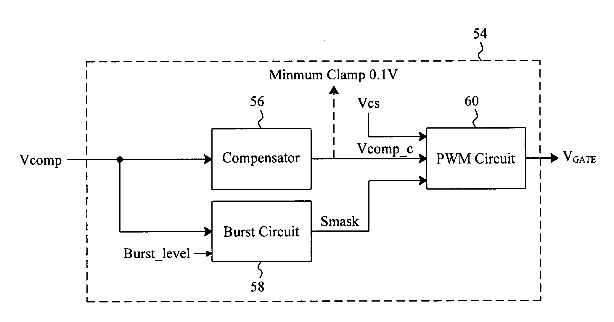
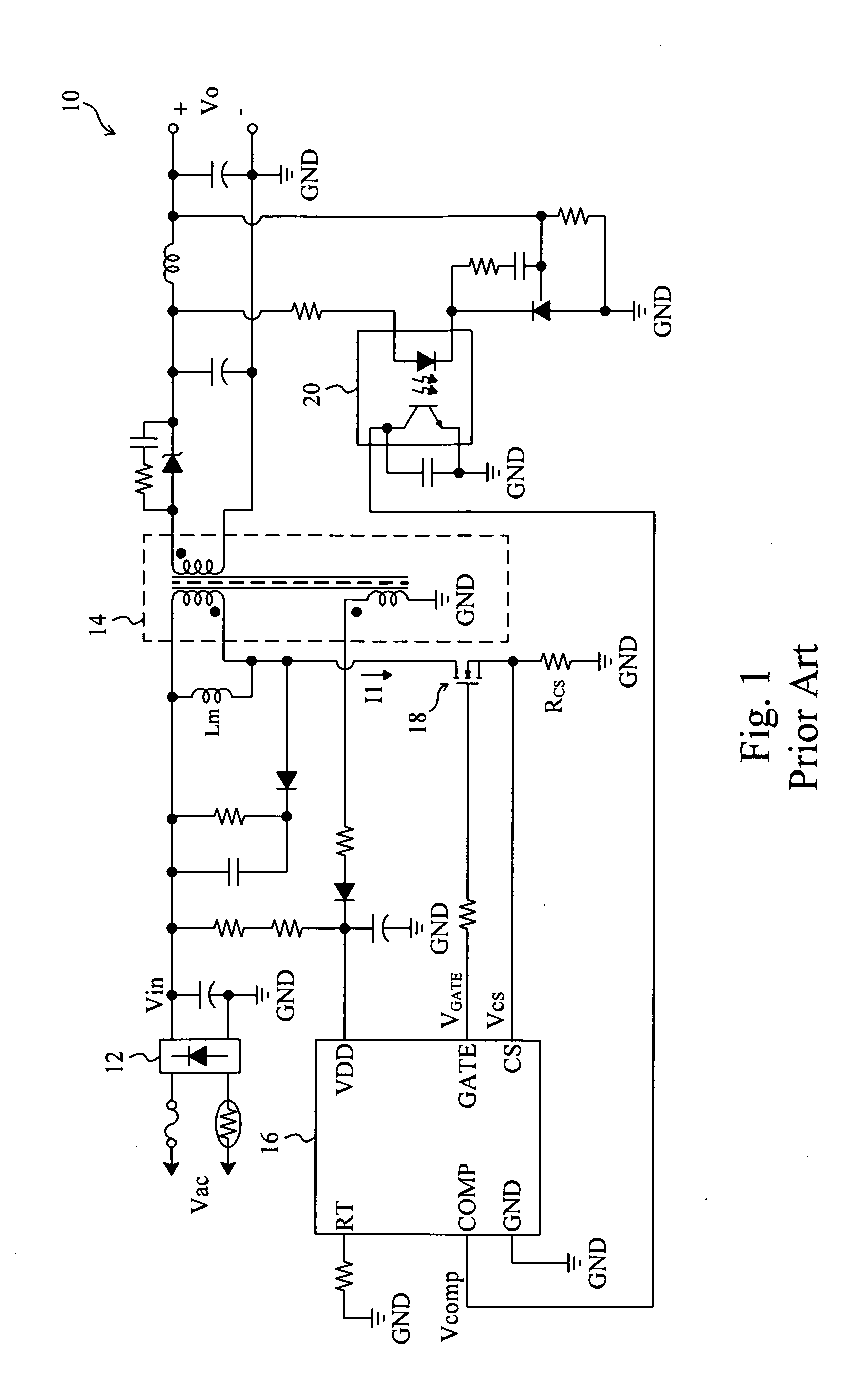
[0020]FIG. 6 is a perspective diagram of a first embodiment according to the present invention. The controller 16 shown in FIG. 2 is now replaced by the control circuit 54 shown in FIG. 6 to be used in FIG. 1. In the control circuit 54, a compensator 56 compensates the feedback signal Vcomp to generate a compensated feedback signal Vcomp_c, a burst circuit 58 generates a mask signal Smask according to the feedback signal Vcomp and the preset voltage Burst_level to determine whether or not the flyback converter 10 to enter the burst mode, and a PWM circuit 60 generates the control signal VGATE according to the current sense signal Vcs, the compensated feedback signal Vcomp_c, and the mask signal Smask, to switch the power switch 18. FIG. 7 is a perspective diagram of the details of the control circuit 54 shown in FIG. 6. As shown in FIG. 7, the compensator 56 includes an adder 62 having a positive input 622 to receive the feedback signal Vcomp, a negative input 624 to receive a sawto...

second embodiment

[0023]FIG. 10 is a perspective diagram of a second embodiment according to the present invention, in which a control circuit 80 also includes the burst circuit 58, the PWM circuit 60 and the AND gate 66. The control circuit 80 further includes a compensator 82 to compensate the current sense signal Vcs to generate a compensated current sense signal Vcs_c. The comparator 68 in the PWM circuit 60 compares the compensated current sense signal Vcs_c with the feedback signal Vcomp to generate the signal S2, which is then supplied to the reset input R of the flip-flop 70. The compensator 82 includes an adder 84 having two positive inputs 842 and 844 to receive the current sense signal Vcs and the sawtooth wave Sramp respectively, and an output 846 to provide the compensated current sense signal Vcs_c. Similarly, after the current sense signal Vcs is compensated with the sawtooth wave Sramp, the peak value of the current I1 flowing through the power switch 18 will remain substantially the ...


PUM


Abstract

A control circuit and method are provided for a flyback converter converting an input voltage to an output voltage, to compensate for an entry point of a burst mode of the flyback converter, so that the entry point is not affected by the input voltage, and audible noise resulted from a higher input voltage is reduced without impacting the light load efficiency of the flyback converter.

Description

FIELD OF THE INVENTION[0001]The present invention is related generally to a flyback converter and, more particularly, to a control circuit and method for a flyback converter.BACKGROUND OF THE INVENTION[0002]All electrical devices are required a power source for operation. Among the various types of power supplies, switching power converters are widely used because they have better efficiency and provide suitable output modulation. However, when a switching power converter is under light load conditions, its efficiency will reduce due to switching loss. To improve the efficiency at light load, a burst mode strategy is applied to reduce the average switching frequency and save the switching loss. FIG. 1 is a perspective diagram of a conventional current mode flyback converter 10, in which a rectifier 12 converts an AC voltage Vac into a DC input voltage Vin, a controller 16 detects the current flowing through a power switch 18 to obtain a current sense signal Vcs, and provides a contr...

Claims


Application Information

Patent Timeline
IPC IPC(8): H02M3/335
CPCH02M3/335H02M3/33507Y02B70/16H02M2001/0032Y02B70/10H02M1/0032
Inventor LIN, TZU-CHENHUANG, PEI-LUN
Owner RICHTEK TECH
Why Eureka
Try Eureka