
Fluid machine

Inactive Publication Date: 2009-11-19
TOYOTA IND CORP
View PDF8 Cites 6 Cited by
  • Summary
  • Abstract
  • Description
  • Claims
  • Application Information

AI Technical Summary

Benefits of technology

[0009]Accordingly, it is an objective of the present invention to provide a fluid machine that simplifies adjustment after assembly of a housing and prevents a bearing from separating from the housing when the housing is assembled.

Problems solved by technology

As a result, the vacuum pump of Patent Document 1 requires complicated assembly of the housing and complicated readjustment after completion of the assembly of the housing.
Further, if the upper casing member is joined to the lower casing member in this state, the fluid machine is assembled with the phase difference maintained as an inappropriate value.

Method used


Image

  • Fluid machine
  • Fluid machine
  • Fluid machine

Examples


first embodiment

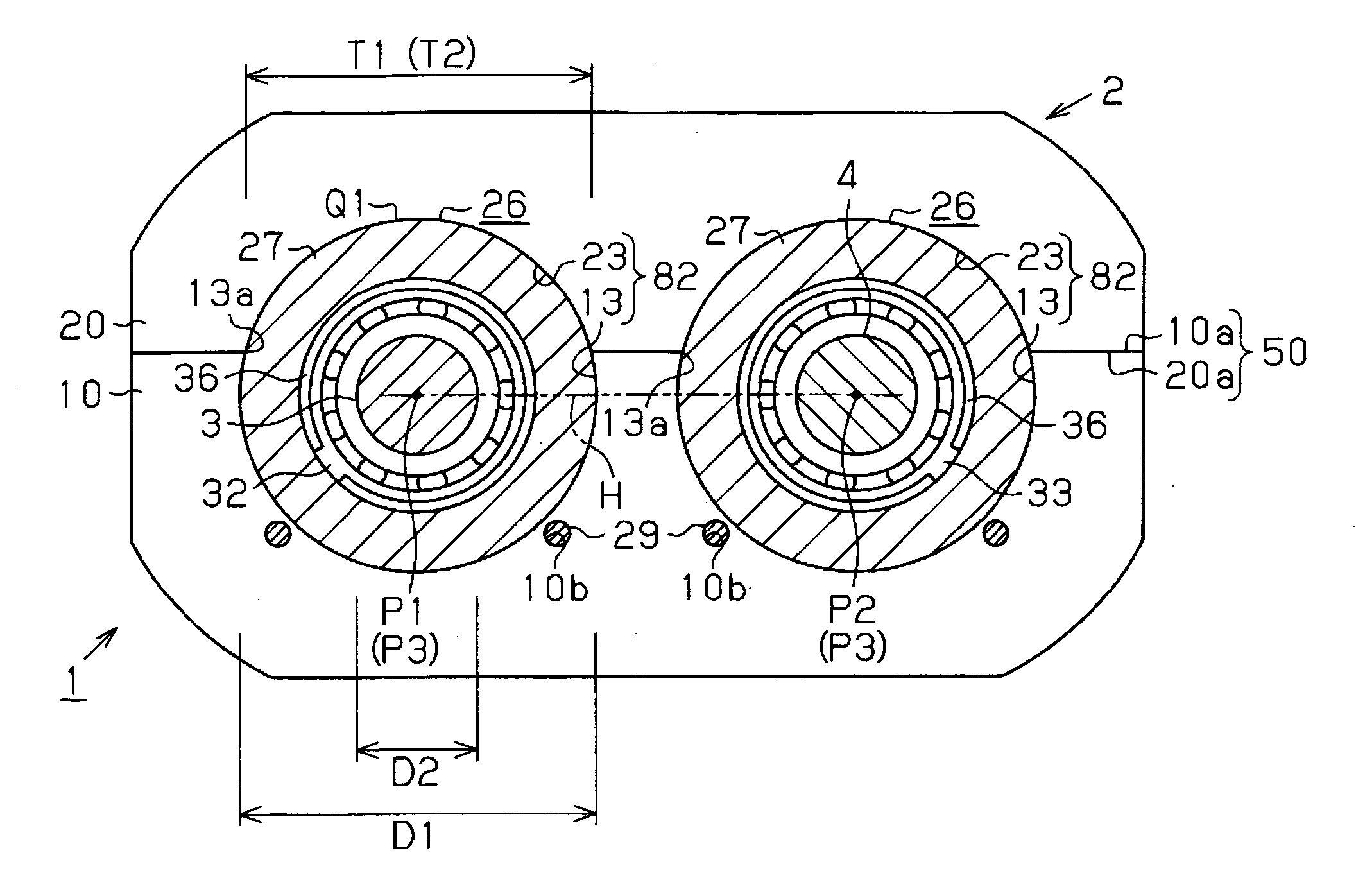
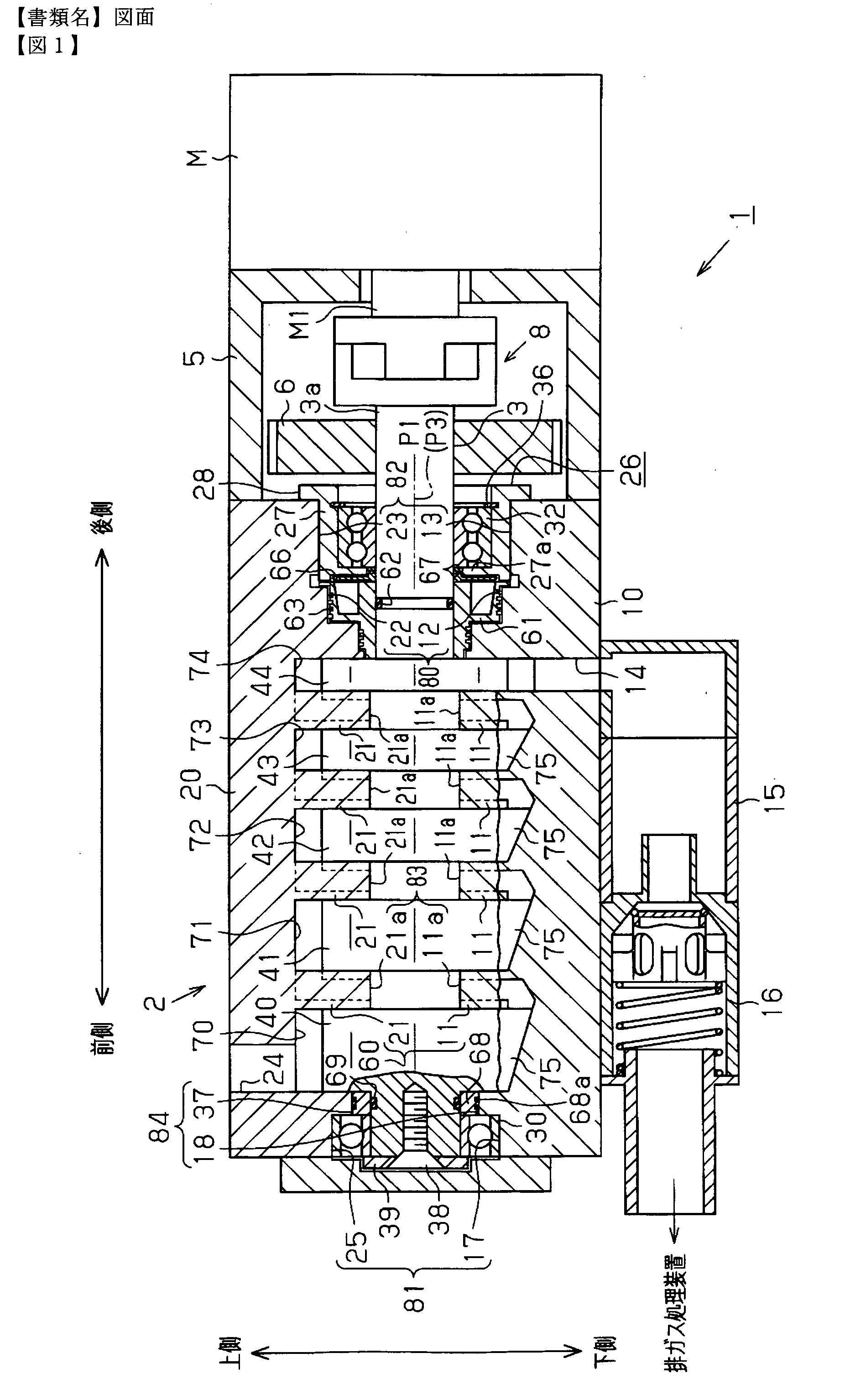
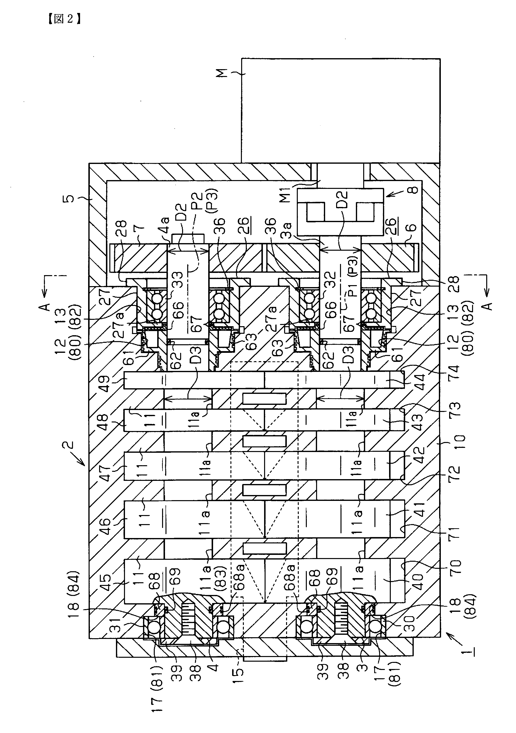
[0019]a fluid machine according to the present invention, or a Roots pump 1, will now be described with reference to FIGS. 1 to 6. In the following description, an upper side of FIG. 1 corresponds to an upper side of the Roots pump 1, and a lower side of the drawing corresponds to a lower side of the Roots pump 1. Also, a left side of the drawing corresponds to a front side of the Roots pump 1, and a right side of the Roots pump 1 corresponds to a rear side of the Roots pump 1.

[0020]As shown in FIG. 1, a housing 2 of the Roots pump 1 has a lower housing member 10 and an upper housing member 20, which is joined to the lower housing member 10. In other words, the housing 2 has a two-piece structure that can be divided into an upper piece and a lower piece. As illustrated in FIG. 3, the upper surface of the lower housing member 10 forms a lower joint surface 10a, which is provided as a flat surface that contacts the upper housing member 20. The entire portion of the lower joint surface...

second embodiment

[0085]A method for assembling the Roots pump 1 will now be explained.

[0086]First, the shafts 3, 4 are received in the lower accommodating portions 11a through the shaft inserting portions 111c, as in the first embodiment. Then, in the front portion of the housing 2, the annular shaft seals 68 are received in the front lower seal accommodating portions 18 and the annular shaft seals 68 are fixed to the corresponding shafts 3, 4. The front bearings 30, 31 are also received in the corresponding front lower support portions 17 and the front bearings 30, 31 are fixed to the corresponding shafts 3, 4 using the positioning bolts 38 and the positioning plate 39.

[0087]Subsequently, the annular shaft seals 61, the slingers 66, and the shims 67 are attached to the corresponding shafts 3, 4 in the rear seal accommodating portions 12 along the axes P1, P2. The rear bearings 32, 33 are then each received in the corresponding lower support portion 13 from behind the lower housing member 10 and se...


PUM


Abstract

A housing of a Roots pump is configured by joining a lower housing member and an upper housing member that are separable from each other. With the upper and lower housing members joined together, an upper accommodating portion and a lower accommodating portion form a front bearing accommodating portion and a rear bearing accommodating portion, which accommodate whole bearings, respectively. The Roots pump further includes bearing holders attached to the bearings and fixed to the lower housing member so that the bearings are received in the lower accommodating portion in a positioned state.

Description

TECHNICAL FIELD[0001]The present invention relates to a fluid machine that transports fluid by rotating a rotor through rotation of a rotary shaft.BACKGROUND ART[0002]As one such fluid machine, a vacuum pump disclosed in Patent Document 1, for example, has been proposed. The vacuum pump of Patent Document 1 includes a housing formed by a rotor housing member, a front housing member, and a rear housing member. The front housing member is joined to a front end of the rotor housing member. The rear housing member is joined to a rear end of the rotor housing member. The rotor housing member is a cylinder block configured by a pair of upper and lower block pieces. A pair of rotary shafts are rotatably supported by the front housing member and the rear housing member each through a radial bearing. A plurality of rotors are fixed to each of the rotary shafts. The rotary shafts rotate synchronously through engagement between gears each secured to an end of the corresponding rotary shaft. Ea...

Claims


Application Information

Patent Timeline
IPC IPC(8): F04C29/00
CPCF01C1/086F01C1/126F01C11/002F04C2240/56F01C21/02F01C21/10F04C2230/60F01C19/125F04C29/00F04C19/00
Inventor INAGAKI, MASAHIROYAMAMOTO, SHINYAYOSHIKAWA, MAKOTOIZAWA, YUYA
Owner TOYOTA IND CORP
Learn More