Film-covered electrical device packaging system

Active Publication Date: 2009-11-19
NEC CORP
View PDF13 Cites 10 Cited by
  • Summary
  • Abstract
  • Description
  • Claims
  • Application Information

AI Technical Summary

Benefits of technology

[0010]Nevertheless, when a duct is formed in a pressure plate, an overall height of a system will become high by the duct. In addition, a construction adopting a duct as a different part will cause an increase in the number of parts that are used.
[0011]On the other hand, when a groove is formed in a pressure plate, rigidity of the portion of the plate where the groove is formed decreases, and hence in such a case applying uniform pressure to a battery becomes impossible.
[0012]Then, the present invention aims to provide a film-covered electrical device packaging system which can apply uniform pressure to a battery, and in which an increase in the overall height of a system is prevented.
[0015]Therefore, even if the pressure plate is used in which the rigidity distribution of the plate is not uniform because of the gas guide groove being formed, it is possible to prevent uneven pressure from being applied to the electrical device element.
[0016]In addition, since the channel for guiding gas from the through hole to the sidewall face is groove-shaped, in comparison with a duct form extending to the outside, it is possible to lower the overall height of a system. Furthermore, since the channel for guiding a gas to the outside is a groove, it is not necessary to form a channel by using a different part such as a duct, and hence, the number of parts can be reduced.
[0021]As mentioned above, the pressure plates of the present invention sandwiches the frame member which has a portion thicker than the thickness of the electrical device element. For this reason, a space is formed between the electrical device element and the pressure plate, and, therefore, uniform atmospheric pressure is applied to the electrical device element. Thus, according to the present invention, even if a gas guide groove is formed in the pressure plate, it is possible to prevent uneven pressure from being applied. In addition, since the channel for guiding gas from the through hole to the sidewall face is groove-shaped, in comparison with a duct form extending to the outside, it is possible to lower the overall height of a system. Furthermore, since the channel for guiding a gas to the outside is made into a groove, it is not necessary to form a channel by using a different part such as a duct, and hence, the number of parts can be reduced.

Problems solved by technology

In addition, a construction adopting a duct as a different part will cause an increase in the number of parts that are used.
On the other hand, when a groove is formed in a pressure plate, rigidity of the portion of the plate where the groove is formed decreases, and hence in such a case applying uniform pressure to a battery becomes impossible.

Method used


Image

  • Film-covered electrical device packaging system
  • Film-covered electrical device packaging system
  • Film-covered electrical device packaging system

Examples


Embodiment Construction

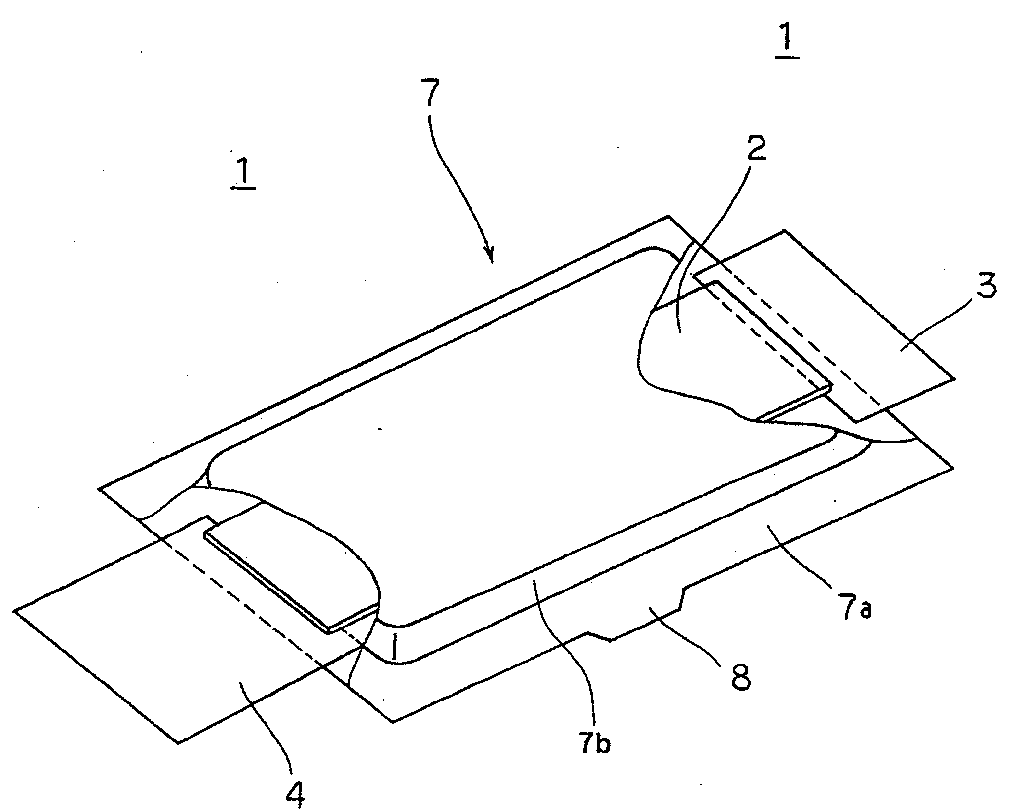
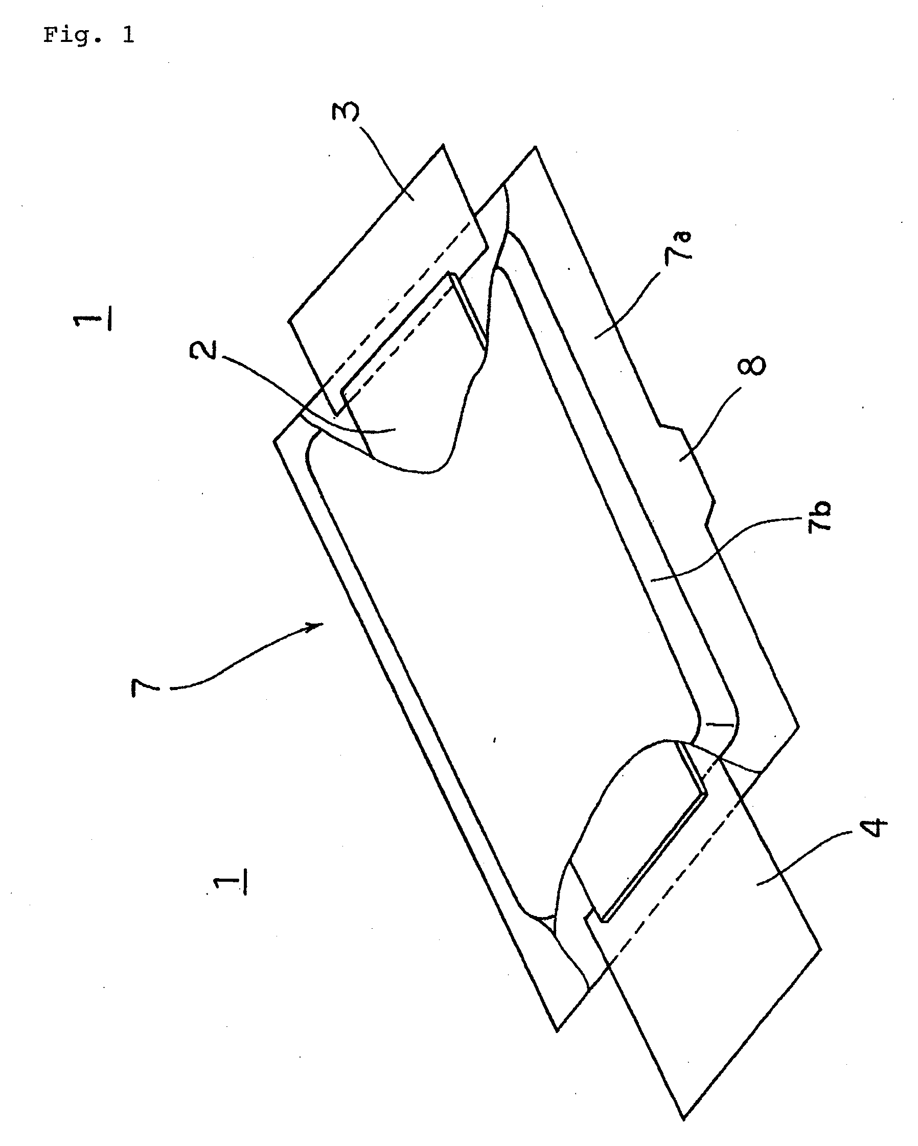
[0027]An external perspective view of the film covered battery of this exemplary embodiment is illustrated in FIG. 1.

[0028]Film-covered battery 1 of this exemplary embodiment has battery element 2 which has a positive active electrode, a negative active electrode, and an electrolyte, laminated film 7 which is formed by arranging a metallic film, such as aluminum, and a heat-sealing resin film, in stack. Film-covered battery 1 has structure made of sealing battery element 2 that has two sheets of laminated film 7. That is, film-covered battery 1 of this exemplary embodiment is made into a bag by heat-sealing the first three sides among thermally fused portions 7a which are four sides of laminated film 7. Then, evacuation is performed by internal air being evacuated from one remaining open side. After that, battery element 2 is hermetically sealed with two sheets of laminated film 7 heat-sealing by one remaining side of thermally fused portions 7a. In addition, it is also sufficient t...


PUM


Abstract

A film-covered electrical device packaging system of the present invention includes frame member (10) which holds film covered battery (1) by an outer periphery portion of film covered battery (1) and which has a portion thicker than the thickness of power generation element (2), and in which waste gas channel (10i) is formed in a position corresponding to gas discharger (8), and first pressure plate (20) which sandwiches frame member (10), in which penetrating portion (22) is formed in a position corresponding to waste gas channel (10i), and in which gas guide groove (21) communicating from through holes (22) to sidewall face (24) is formed.

Description

TECHNICAL FIELD[0001]The present invention relates to a film-covered electrical device packaging system which packages a film-covered electrical device.BACKGROUND ART[0002]Recently, the development of electric vehicles and hybrid electric vehicles (hereafter, this is called simply “an electric vehicle and the like”) each carrying a battery for a motor drive has been advanced rapidly. In order to enhance steering characteristics and cruising range, naturally, light weight and a thin profile are requested also for a battery mounted in an electric vehicle and the like. In order to make a battery light and thin, a film covered battery has been developed using laminate material which is made into a film by superposing a metal layer, such as aluminum, and a thermal welding resin layer on the case body through an adhesive layer, and making them thin. Generally, the laminate material has a structure in which both surfaces of a thin metal layer, such as aluminum are coated, with a thin resin...

Claims


Application Information

Patent Timeline
IPC IPC(8): H01M2/12H01M10/60H01M10/613H01M10/625H01M10/647H01M10/6556H01M10/6557H01M10/6563H01M50/119H01M50/121H01M50/124H01M50/211H01M50/291
CPCH01M2/0257H01M2/0287H01M2/1016H01M10/52H01M10/5004H01M10/5016H01M10/5073H01M2/12H01M10/625H01M10/6566H01M10/613Y02E60/10H01M50/124H01M50/30H01M50/119H01M50/291H01M50/121H01M50/211
Inventor SHIMAMORI, TADASHI
Owner NEC CORP
Why Eureka
Try Eureka