Apparatus and method for estimating location using multi-antenna radio receiver

a multi-antenna radio receiver and antenna technology, applied in the electrical field, can solve the problems of large error variance, large channel coherence time, and very slow change of wireless channels, and achieve the effect of accurately estimating the position of objects

Active Publication Date: 2009-11-19
TERRACE LICENSING LLC
View PDF2 Cites 78 Cited by
  • Summary
  • Abstract
  • Description
  • Claims
  • Application Information

AI Technical Summary

Benefits of technology

[0008]One or more embodiments of the invention may offer one or more technical benefits; for example, accurately estimating the position of an object, such as a relatively slowly moving object, in an indoor environment.

Problems solved by technology

The location position estimates obtained from radio signal strength measurements in a location positioning system using single-antenna radio transceivers are reliable and stable in the long term, but suffer from a large error variance due to the fading radio channel.
In a typical indoor environment, however, the wireless channel changes very slowly, i.e. the channel coherence time is large.
Therefore, position estimates derived from signal strength measurements with a single-antenna receiver can only be updated rather infrequently and are not well-suited for tracking the location position of a moving object.

Method used


Image

  • Apparatus and method for estimating location using multi-antenna radio receiver
  • Apparatus and method for estimating location using multi-antenna radio receiver
  • Apparatus and method for estimating location using multi-antenna radio receiver

Examples


Embodiment Construction

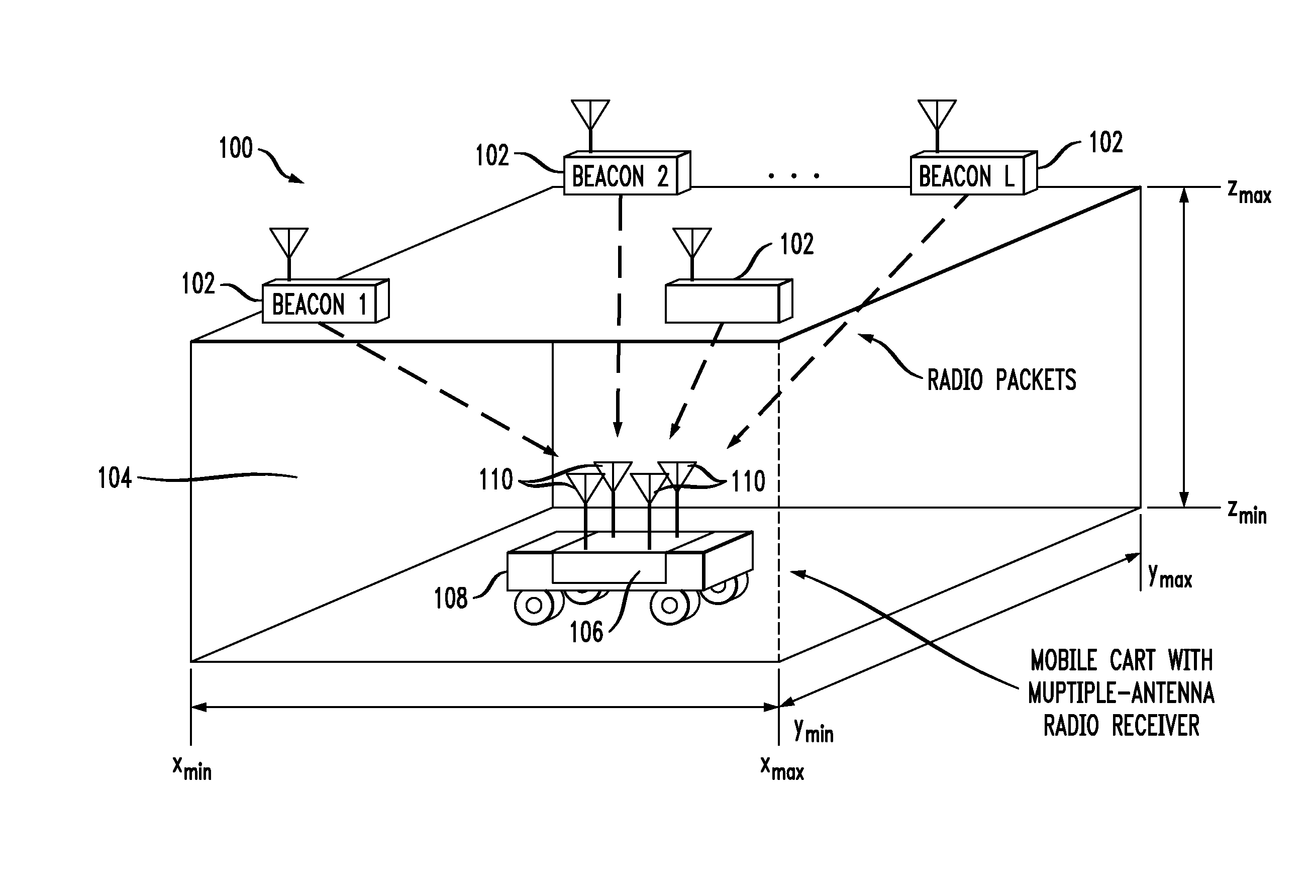
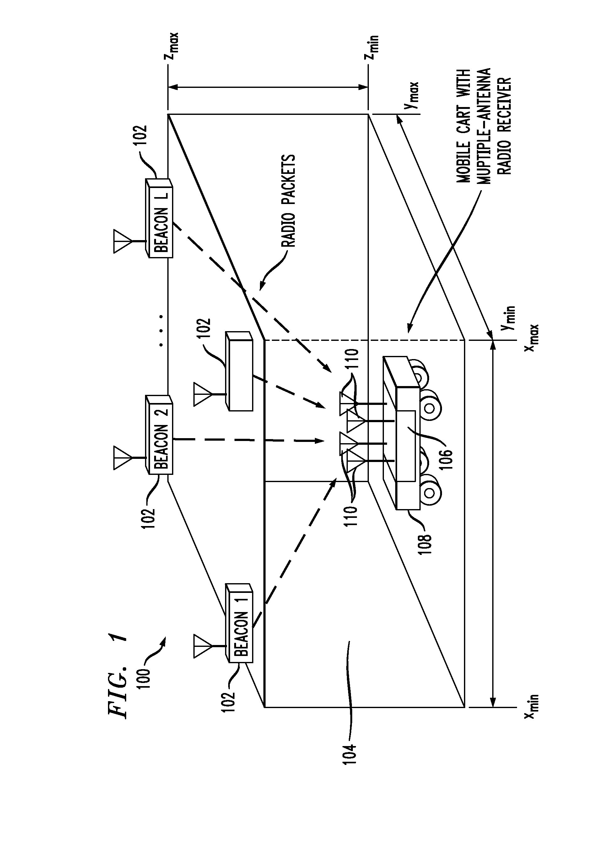
[0016]Aspects of the invention provide techniques for accurately measuring the position of a mobile object in an indoor environment. The location estimates can be derived from received signal strength measurements of radio signals that are transmitted by radio beacons deployed at known location positions in the building. Accurate location estimates are obtained by averaging, not only in time, but also in space, the signal strength measurements made in a multi-antenna radio receiver. One or more embodiments take into account spatial constraints given by the floor plan of the building. The object is preferably static or slowly moving. A multi-antenna radio receiver can be mounted to the object.

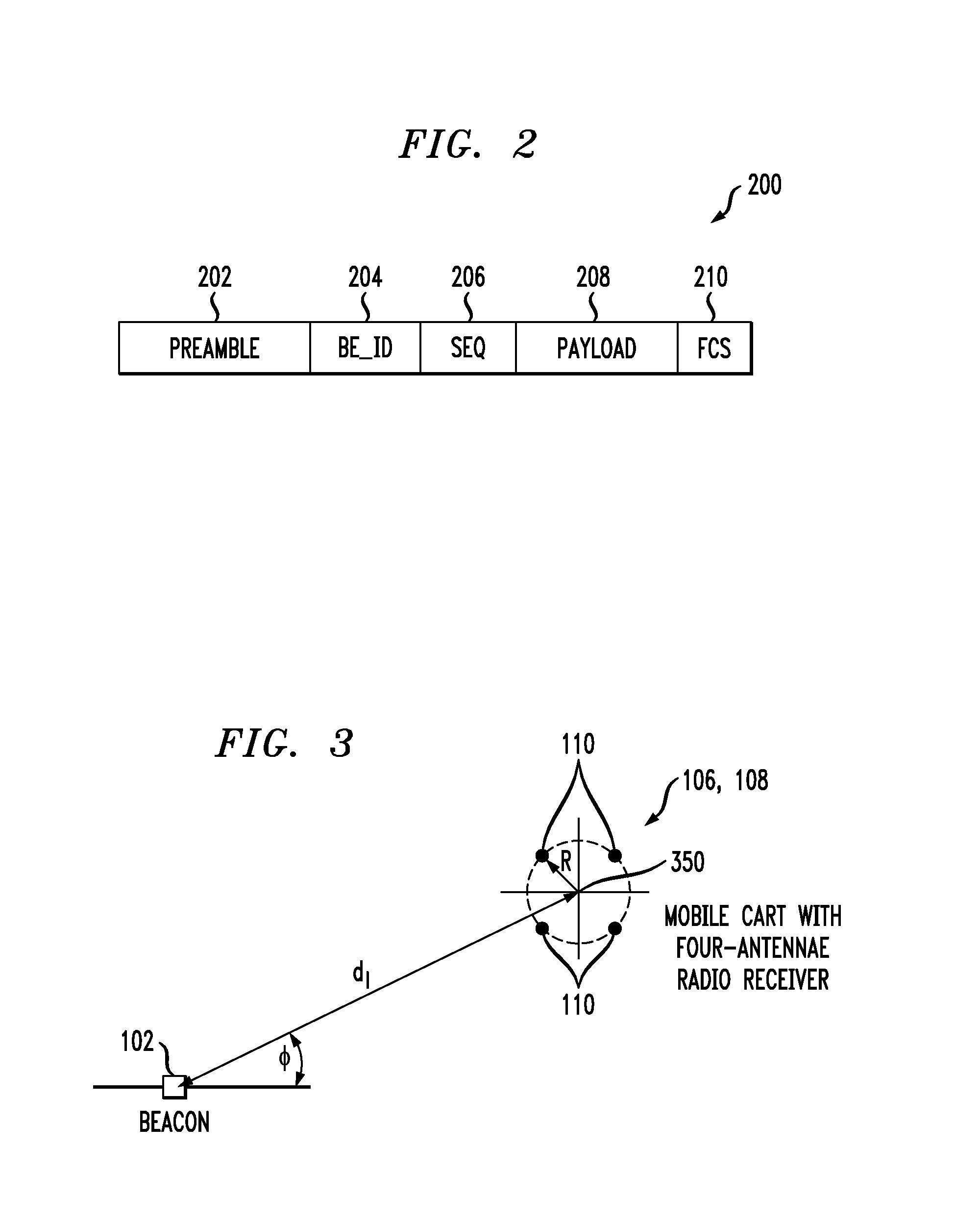
[0017]With reference to FIG. 1, in one aspect, a wireless location positioning system 100 is disclosed, where L radio beacons 102 are deployed at known positions over the location estimation area 104. Each beacon 102 periodically transmits a radio packet containing its identifier and a unique se...


PUM


Abstract

Packets are periodically transmitted by a plurality of radio beacons deployed at known positions over a location estimation area. Monitoring is conducted for incoming packets. Upon receipt of a packet from a kth one of the beacons, received signal strength, RSSI, is measured at each of the antenna outputs, the packet is decoded to obtain the unique identifier and the unique sequence number, and the received signal strength at each of the antenna outputs is spatially averaged. The measuring, decoding, and spatial averaging are repeated for additional packets from the kth one of the beacons during a pre-defined time window T. The plurality of spatially averaged received signal strengths are temporally averaged over the pre-defined time window T, to obtain a spatially and temporally averaged value of received signal strength. The distance dk from the apparatus to the kth one of the beacons is approximated based on the spatially and temporally averaged value of received signal strength. The approximate distance dk is designated as {circumflex over (d)}k. This is repeated for the K beacons that have successfully transmitted packet(s) during the pre-defined time window, k=1 to K. The location of the object is estimated as an approximate intersection of spheres with radii {circumflex over (d)}k. Each sphere is centered at the known position of the kth one of the beacons.

Description

FIELD OF THE INVENTION[0001]The present invention relates to the electrical, electronic and computer arts, and, more particularly, to location estimation and the like.BACKGROUND OF THE INVENTION[0002]Location sensing of slowly moving objects in an indoor environment has created a growing interest in location-aware services and applications in various market segments. In the retail industry, for example, shopping carts equipped with a personal shopping assistant enriched with some additional location positioning functionality can guide customers through a store, provide them with location-based product information, and alert them to promotions and discounts as they walk through the aisles. However, customer satisfaction, and thereby the success of this advanced shopping service, depends on the achievable position accuracy.[0003]Location tracking of mobile objects in an indoor environment can be performed with various techniques, based on mechanical, acoustical, ultra-sonic, optical, ...

Claims


Application Information

Patent Timeline
Patent Type & Authority Applications(United States)
IPC IPC(8): H04Q7/20
CPCH04W4/20G01S5/14
Inventor CORONEL, PEDRO E.SCHOTT, WOLFGANG H.WEISS, BEAT
Owner TERRACE LICENSING LLC
Why Eureka
Try Eureka