Luminal clip applicator with sensor and methods for occluding body lumens

a technology of occluding body lumens and applicators, which is applied in the field of medical devices, can solve the problems of difficult to distinguish between blood vessels, ducts, other tissues, and many physicians do not possess the skill or equipment necessary to perform catheter-based uterine artery embolization, etc., and achieves convenient and accurate deployment of luminal clips. , the effect of minimizing the risk of misapplication

Inactive Publication Date: 2009-11-19
VASCULAR CONTROL SYST
View PDF100 Cites 4 Cited by
  • Summary
  • Abstract
  • Description
  • Claims
  • Application Information

AI Technical Summary

Benefits of technology

[0014]Luminal clip applicators with sensors embodying features of the invention may be used to apply luminal clips to occlude body lumens, providing a single device or system configured for both the detection of target body lumens and for the placement of luminal clips onto them. Unlike prior art clip applicators, such a luminal clip applicator with a sensor facilitates the accurate deployment of the clip and provides the advantage of being able to differentiate between a duct and a blood vessel. This minimizes the risk of misapplication of a luminal clip. These devices and methods for applying luminal clips are simpler and more readily used than other methods and devices, and provide improved treatments for serious conditions and diseases, including uterine fibroids, adenomyosis, dysfunctional uterine bleeding (DUB), postpartum hemorrhage, and for other uterine disorders. Devices, systems and methods embodying features of the invention provide tools and methods for effective treatment of diseases and conditions that might otherwise require invasive and irreversible treatments such as removal of a uterus.

Problems solved by technology

However, it is often difficult to distinguish between blood vessels, ducts, and other tissues, and to identify the proper tissue to which to apply a luminal clip.
However, hysterectomy is a drastic treatment, having many undesirable characteristics.
However, many physicians do not possess the skill or equipment necessary to perform catheter-based uterine artery embolization under radiologic direction.

Method used


Image

  • Luminal clip applicator with sensor and methods for occluding body lumens
  • Luminal clip applicator with sensor and methods for occluding body lumens
  • Luminal clip applicator with sensor and methods for occluding body lumens

Examples


Embodiment Construction

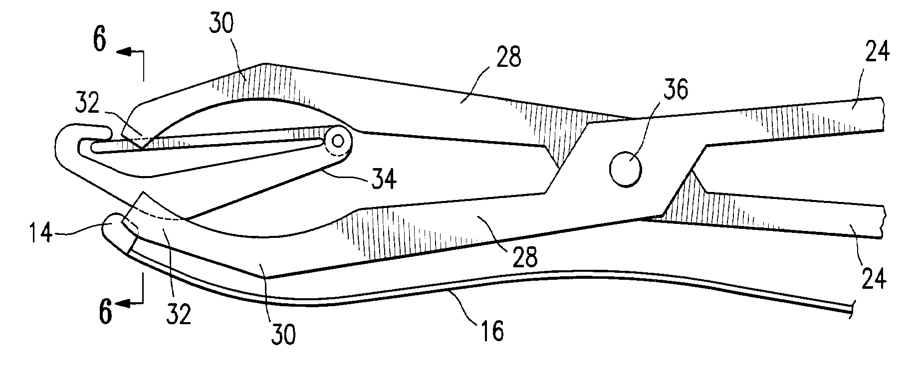
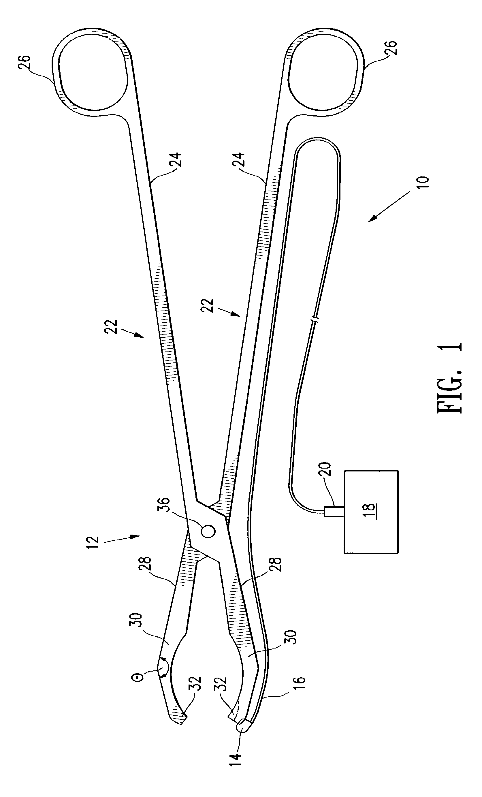
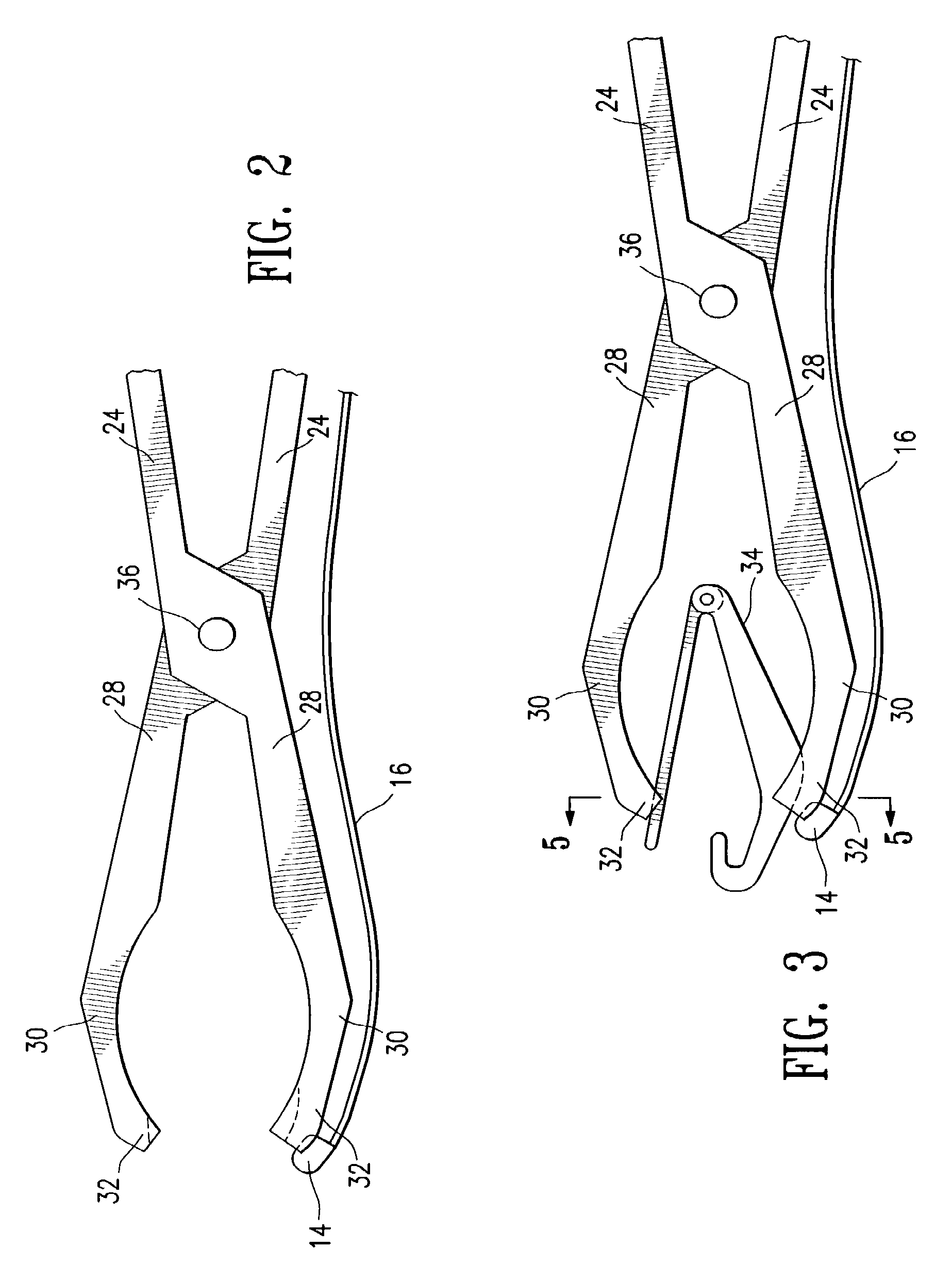
[0024]FIGS. 1-6 show a luminal clip applicator system 10 embodying features of the invention. The system 10 includes a clip-applying device 12, a body lumen sensor 14 and an energy transmission member 16, e.g. a conductor, connected to the body lumen sensor 14 and configured to be operatively connected to a sensor controller 18 (e.g., via a connector 20).

[0025]The clip-applying device 12 has elongated members 22 having proximal handle portions 24 with finger holes 26 and distal jaw portions 28 with jaws 30. Jaws 30 have pressure-applying surfaces 32 configured to engage and hold a luminal clip 34 (e.g., as shown in FIGS. 3-6). Elongated members 22 are pivotally connected at pivot point 36 located proximal to the jaws 30, so that squeezing proximal handle portions 24 together closes jaws 30, compressing a luminal clip 34 as shown in FIGS. 4-6. A jaw 30 and a pressure-applying surface 32 may have a clip-engaging feature 38, such as a slot or ridge, or other feature configured to relea...


PUM


Abstract

A method for occluding a body lumen includes providing a clamping device having a pair of opposed pressure applying jaws, providing a sensor on one of the pressure applying jaws for sensing blood flow through a body lumen, and releasably securing a luminal clip between the pressure applying jaws. The method includes using the sensor for detecting blood flow through the body lumen for locating the body lumen, positioning the luminal clip adjacent the located body lumen, and closing the pressure applying jaws for clamping the luminal clip over the body lumen for at least partially occluding blood flow through the body lumen.

Description

CROSS-REFERENCE TO RELATED APPLICATIONS[0001]This application is a continuation of U.S. patent application Ser. No. 10 / 300,410, filed Nov. 19, 2002, which is a continuation-in-part of U.S. patent application Ser. No. 10 / 113,096, filed Mar. 28, 2002, which claims the benefit of U.S. Provisional Application Ser. No. 60 / 279,477, filed Mar. 28, 2001, which applications are hereby incorporated by reference herein in their entirety and from which priority is hereby claimed under 35 U.S.C. § 119(e) and 35 U.S.C. § 120.FIELD OF THE INVENTION[0002]The present invention relates generally to the field of medical devices and treatments of diseases and conditions by the detection and occlusion of internal body lumens such as blood vessels and ducts by application of luminal clips.BACKGROUND OF THE INVENTION[0003]Many surgical procedures, including tubal ligation, cholecystectomy, appendectomy, liver biopsy, and other procedures, often require the placement of a luminal clip, typically to occlude...

Claims


Application Information

Patent Timeline
Patent Type & Authority Applications(United States)
IPC IPC(8): A61B17/08A61B5/0215A61B8/14A61B17/10A61B5/026A61B8/06A61B17/00A61B17/122A61B17/128A61B17/42
CPCA61B5/026A61B5/415A61B5/418A61B8/06A61B8/12A61B17/00234A61B2017/4216A61B17/122A61B17/128A61B17/1285A61B17/2812A61B17/42A61B2017/0046A61B17/12
Inventor BURBANK, FRED H.JONES, MICHAEL L.SERRA, R.J.ALTIERI, GREIG E.ULYENO, JILLWONG, YU-TUNGWERNETH, RANDY
Owner VASCULAR CONTROL SYST
Why Eureka
Try Eureka