
Medical diagnostic instrument having portable illuminator

a diagnostic instrument and portable technology, applied in the field of diagnostic medicine, can solve the problems of contamination, versatility and ease of use, and introduce contamination, and achieve the effects of eliminating time and expense of reprocessing and cleaning, facilitating the use of hand-held diagnostic instruments, and reducing the degree of user versatility

Active Publication Date: 2009-11-19
WELCH ALLYN INC
View PDF109 Cites 158 Cited by
  • Summary
  • Abstract
  • Description
  • Claims
  • Application Information

AI Technical Summary

Benefits of technology

[0011]The handle portion can include at least one retaining feature for retaining said illuminator in said receiving cavity. In one version, the handle portion further includes at least one feature for facilitating release of the portable illuminator from the handle portion. According to one embodiment, at least a portion of said handle portion can be flexibly deformable.
[0017]One advantage of the herein described assembly is greater degree of user versatility achieved by providing at least one medical diagnostic instrument that releasably accepts a portable illuminator. Another advantage provided is greater ease of use of hand-held diagnostic instruments so equipped. Yet another advantage is the ability to develop disposable component(s) to prevent cross contamination during procedures and thereby substantially eliminate time and expense of reprocessing and cleaning.
[0018]Another advantage is that instruments so configured can be provided with improved and consistent ergonomics, enabling better “feel” for the user. Yet another advantage is that portability of a common illuminator enables selectivity of light sources, such as LEDs, providing greater selectivity between different color temperatures and therefore affording choices as to illumination sources and enabling improvements to be added simultaneously to a family of instruments. As such, improved visualization of an examination area is possible by supplying whiter, brighter light. Yet another advantage is that the handle portion can be made disposable, but without creating environmental issues.

Problems solved by technology

The use of corded illumination assemblies, however, introduced issues relating to contamination, versatility and ease of use.
Though effective in terms of this aim, there are subsidiary issues relating to having to provide an on-hand inventory of sheath members, as well as waste disposal and environmental concerns.

Method used


Image

  • Medical diagnostic instrument having portable illuminator
  • Medical diagnostic instrument having portable illuminator
  • Medical diagnostic instrument having portable illuminator

Examples


Embodiment Construction

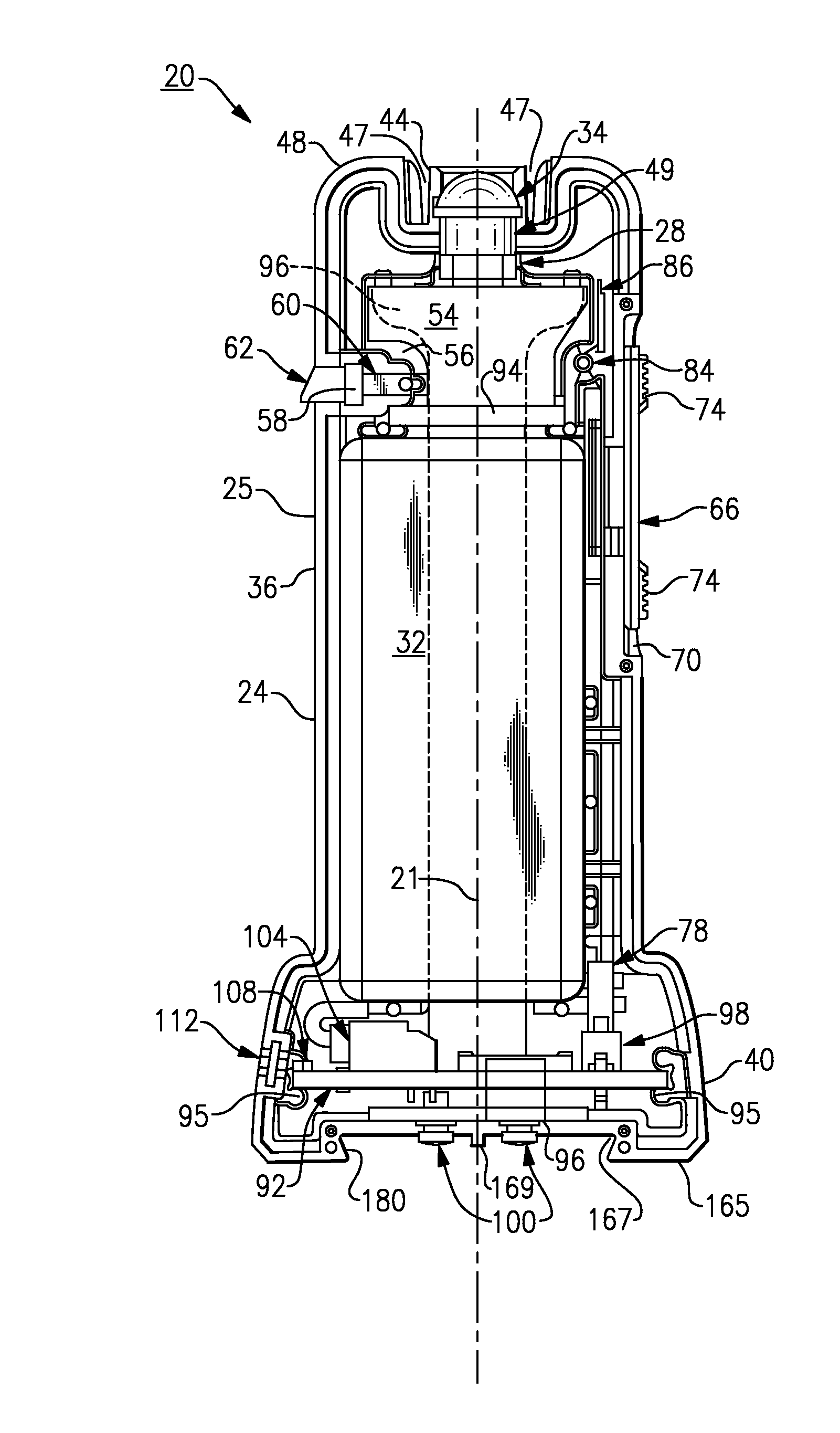
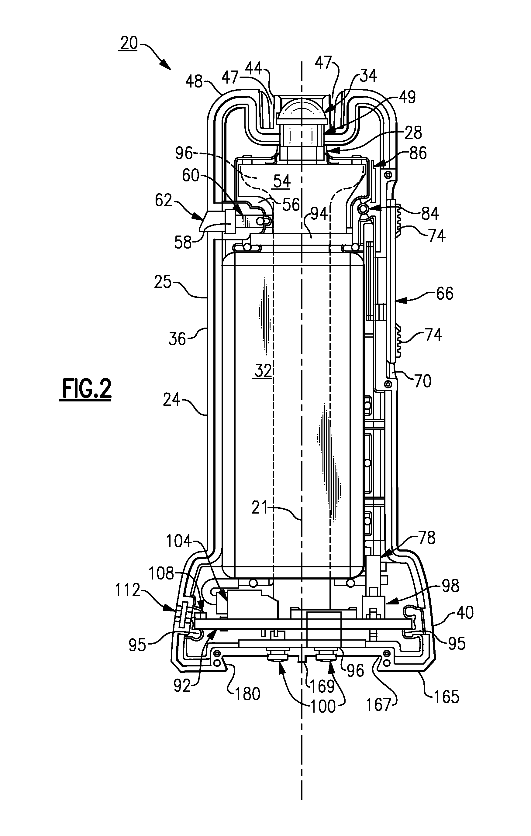
[0054]The following discussion relates to various embodiments of a compact or portable illuminator that can be used in conjunction with either one or a plurality of various hand-held medical diagnostic instruments, including various designs of these instruments, in order to permit incorporation of the compact illuminator. Throughout the course of discussion, similar parts will be labeled with the same reference numerals for the sake of clarity of explanation. In addition, several terms such as “upper”, “lower”, “above”, “within”, “lateral”, “upon”, “below”, “top”, “bottom” and the like are used throughout this discussion in order to provide a suitable frame of reference with regard to the accompanying drawings. It should be understood that these terms are not intended to be limiting, however, except where so specifically indicated.

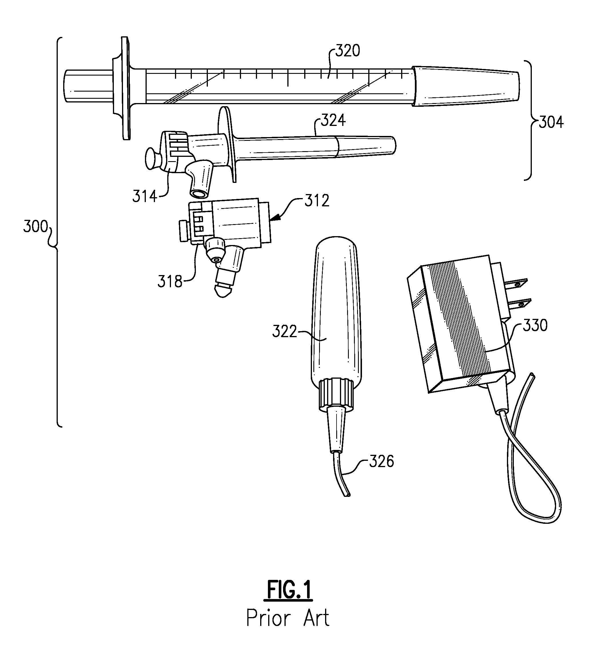
[0055]Referring to FIG. 1 and for background purposes, there is first shown a group 300 of prior art hand-held medical diagnostic instruments, in this ins...


PUM


Abstract

A portable medical diagnostic instrument includes an instrument head and a handle portion having an open-ended receiving cavity. A compact illuminator defined by a housing retaining a miniature light source and a power supply is releasably fitted within the open-ended receiving cavity of the handle portion wherein the light source of the illuminator is optically coupled with the instrument on assembly therewith. The handle portion can be integral with the instrument or releasably attached. The handle portion according to at least one version is made from a plastic or other suitable material, permitting disposability and / or single patient use. In one version, the handle portion is flexibly deformable, at least partially, to facilitate release of the portable illuminator.

Description

CROSS REFERENCE TO RELATED APPLICATIONS[0001]This patent application claims priority upon a provisional application, U.S. Ser. No. 61 / 130,951, filed Jun. 4, 2008, pursuant to 35 USC §119(e). This application is a continuation-in-part (CIP) of the following corresponding United States applications pursuant to 35 USC §120; namely, U.S. Ser. No. 11 / 910,387, filed Apr. 25, 2008, which is a national stage application of PCT / US2006 / 012116, filed Apr. 3, 2006, which claims benefit of U.S. Ser. No. 60 / 735,576, filed Nov. 10, 2005 and U.S. Ser. No. 60 / 667,505, filed Apr. 1, 2005; U.S. Ser. No. 11 / 910,378, filed Apr. 25, 2008, which is a national stage application of PCT / US2006 / 012320, filed Apr. 3, 2006, which claims benefit of U.S. Ser. No. 60 / 735,576, filed Nov. 10, 2005 and U.S. Ser. No. 60 / 667,505, filed Apr. 1, 2005; and U.S. Ser. No. 11 / 910,399, filed May 7, 2008, which is a national stage application of PCT / US2006 / 012322, filed Apr. 3, 2006, which claims benefit of U.S. Ser. No. 60 / 73...

Claims


Application Information

Patent Timeline
Patent Type & Authority Applications(United States)
IPC IPC(8): A61B17/00F21V33/00
CPCA61B1/00105A61B1/00142A61B1/0669A61B1/0684A61B3/0008A61B1/233A61B1/303A61B1/31A61B1/32A61B1/227
Inventor VIVENZIO, ROBERT L.LIA, RAYMOND A.EDWARDS, IAN K.WAWRO, THADDEUSSLAWSON, STEVEN R.
Owner WELCH ALLYN INC
Learn More