System-level ESD detection circuit

a detection circuit and system-level technology, applied in the field of system-level esd detection circuits, can solve the problems of increasing reliability issues, system-level esd issues, and cmos ics are very susceptible to system-level esd stress, and achieve the effect of easily judging the level of an esd voltag

Active Publication Date: 2009-11-19
AMAZING MICROELECTRONICS
View PDF1 Cites 28 Cited by
  • Summary
  • Abstract
  • Description
  • Claims
  • Application Information

AI Technical Summary

Benefits of technology

[0014]In other embodiments, the ESD detection circuit according to the invention can include two or more sets of diode and resistor. By properly designing the breakdown voltages of the diod

Problems solved by technology

As the scale of devices in ICs has become smaller, the devices have become more vulnerable to Electrostatic discharge (ESD).
Hence, ESD has been one of the most important reliability issues for IC products and must be taken into consideration in the design phase of all ICs.
However, besides the component-level ESD stress, system-level ESD

Method used


Image

  • System-level ESD detection circuit
  • System-level ESD detection circuit
  • System-level ESD detection circuit

Examples


first embodiment

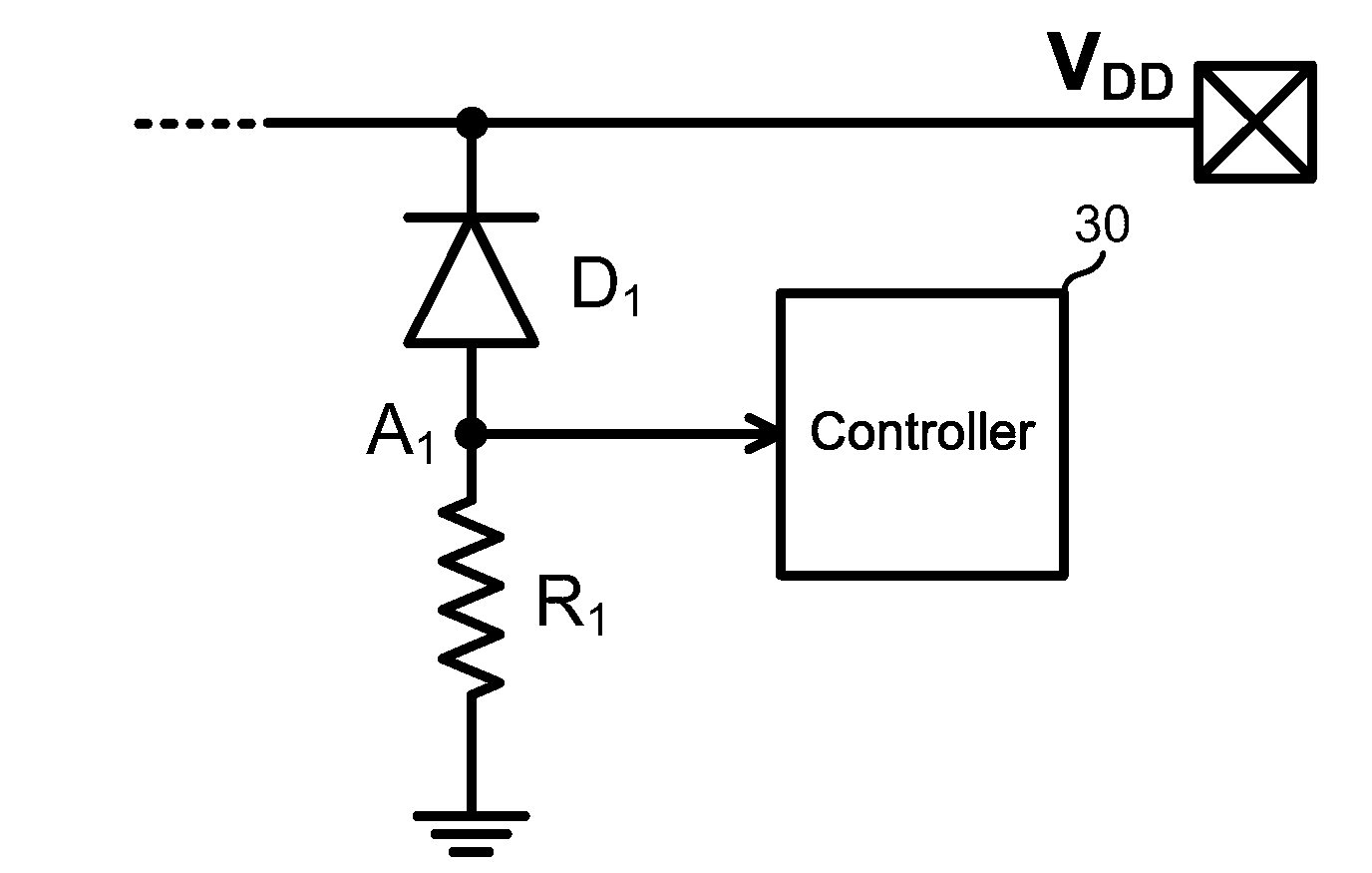
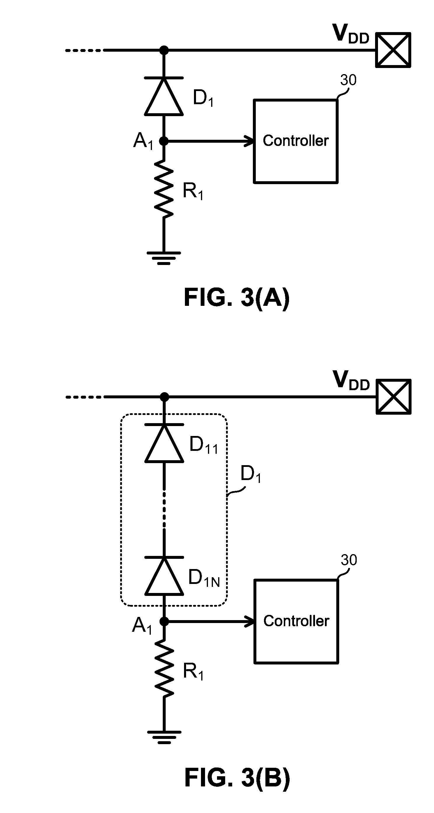
[0021]Please refer to FIG. 3(A), which illustrates the ESD detection circuit in the first embodiment according to the invention. This detection circuit includes a resistive component R1, a diode unit D1, and a controller 30. As shown in FIG. 3(A), the resistive component R1 is coupled between a detection node A1 and a ground node. The diode unit D1 is coupled between a power rail (VDD) and the detection node A1 in a forward direction toward the power rail. The controller 30 is coupled to the detection node A1.

[0022]Under normal circuit operations, the diode unit D1 is reversely biased and the node A1 is grounded through the resistive component R1. When an overshoot voltage happens on VDD, if the diode unit D1 has a breakdown voltage smaller than the overshoot voltage, the diode unit D1 will conduct a current to flow through the resistive component R1. The voltage at node A1 is therefore raised up and equals the product of the conduction current and the resistor value.

[0023]On the co...

second embodiment

[0025]FIG. 4(A) shows the ESD detection circuit in the second embodiment according to the invention. In this embodiment, the detection circuit further includes a resistive component R2 and a diode unit D2. The diode unit D1 has a first breakdown voltage and the diode unit D2 has a second breakdown voltage different from the first breakdown voltage.

[0026]For instance, assume the first breakdown voltage is 10V and the second breakdown voltage is 20V. If an overshoot voltage happens on VDD is larger than 20V, both of the diode units will conduct and the voltages at nodes A1 and A2 are both raised up. On the other hand, if an overshoot voltage ranges between 10V and 20V, only the diode unit D1 will conduct and only the voltage at node A1 is raised up. Different voltage combinations of the detection nodes (A1, A2, . . . An) can indicate different ESD levels. By detecting the voltages at nodes A1 and A2, the controller 30 can easily judge the level of ESD voltages.

[0027]As illustrated in ...


PUM


Abstract

An ESD detection circuit for detecting a level of an ESD voltage on a power rail is provided. The ESD detection circuit includes a resistive component, a diode unit, and a controller. The resistive component is coupled between a detection node and a ground node corresponding to the power rail. The diode unit is coupled between the power rail and the detection node in a forward direction toward the power rail. The controller, coupled to the detection node, is used for determining the level of the ESD voltage based on the voltage of the detection node and the breakdown voltage of the diode unit.

Description

BACKGROUND OF THE INVENTION[0001]1. Field of the Invention[0002]The present invention is related to an electrostatic discharge (ESD) detection circuit. In particular, the present invention relates to a system-level ESD detection circuit.[0003]2. Description of the Prior Art[0004]As the scale of devices in ICs has become smaller, the devices have become more vulnerable to Electrostatic discharge (ESD). Hence, ESD has been one of the most important reliability issues for IC products and must be taken into consideration in the design phase of all ICs.[0005]To meet the component-level ESD reliability, many on-chip ESD protection circuits have been proposed and added to the I / O cells and power cells of CMOS ICs. However, besides the component-level ESD stress, system-level ESD issue is also an increasingly significant reliability issue in CMOS IC products. It has known that some CMOS ICs are very susceptible to system-level ESD stress, even though they have passed the component-level ESD...

Claims


Application Information

Patent Timeline
IPC IPC(8): G01R19/00
CPCG01R31/002G01R19/0053
Inventor KER, MING DOUCHEN, WEN YIJIANG, HSIN CHIN
Owner AMAZING MICROELECTRONICS
Why Eureka
Try Eureka