Icing resistant reduced noise air motor exhaust

a technology of motor exhaust and icing resistance, which is applied in the direction of machines/engines, liquid fuel engines, positive displacement liquid engines, etc., can solve the problems of increasing the duration of noise, reducing noise levels, and reducing peak levels, so as to reduce noise, reduce noise, and minimize downstream exhaust pressure

Inactive Publication Date: 2009-11-26
BEHRENS DAVID M +4
View PDF15 Cites 7 Cited by
  • Summary
  • Abstract
  • Description
  • Claims
  • Application Information

AI Technical Summary

Benefits of technology

[0004]The exhaust manifold directs the exhaust air stream into the muffler such that it creates a thin high velocity air stream creating a low pressure region on both sides of the stream due to the Bernoulli effect. This low pressure region creates a pressure differential which draws the warm external air into the exhaust system. The more external air that is drawn in, the more that icing will be reduced. This requires minimizing downstream exhaust pressure.
[0005]Minimizing downstream exhaust pressure, however, can lead to higher noise levels. In order to reduce noise, a reverberation chamber is added after the muffler exit allowing the sound waves to disperse over time while minimizing backpressure. Reciprocating air motors have a short (15-50 msec.) blast of noise and the reverb chamber reduces peak levels and increases the duration of the noise. The chamber also has a capacitance function which minimizes downstream exhaust pressure.
[0006]The exhaust manifold bolts to the side of the air motor air valve and serves to direct, muffle and diffuse the air motor exhaust using several components. A deflection plate disperses the initial exhaust blast as it leaves the air valve and enters the exhaust manifold. The deflection plate partially deflects the port noise and slows down and spreads out the tightly focused blast thereby reducing noise and exhaust velocity. A diffraction plate in the exhaust manifold diffracts and disperses the exhaust blast through many small holes rather one larger cross-section again reducing noise and exhaust velocity. An expansion chamber is provided in the manifold to direct the exhaust out of the air valve and down the center of the muffler. The muffler cross-section is also split into an expansion chamber and a nozzle with the expansion chamber allowing the exhaust blast to expand and dissipate before exiting the manifold through the diffraction plate and nozzle.

Problems solved by technology

Minimizing downstream exhaust pressure, however, can lead to higher noise levels.
Reciprocating air motors have a short (15-50 msec.) blast of noise and the reverb chamber reduces peak levels and increases the duration of the noise.

Method used


Image

  • Icing resistant reduced noise air motor exhaust
  • Icing resistant reduced noise air motor exhaust

Examples


Embodiment Construction

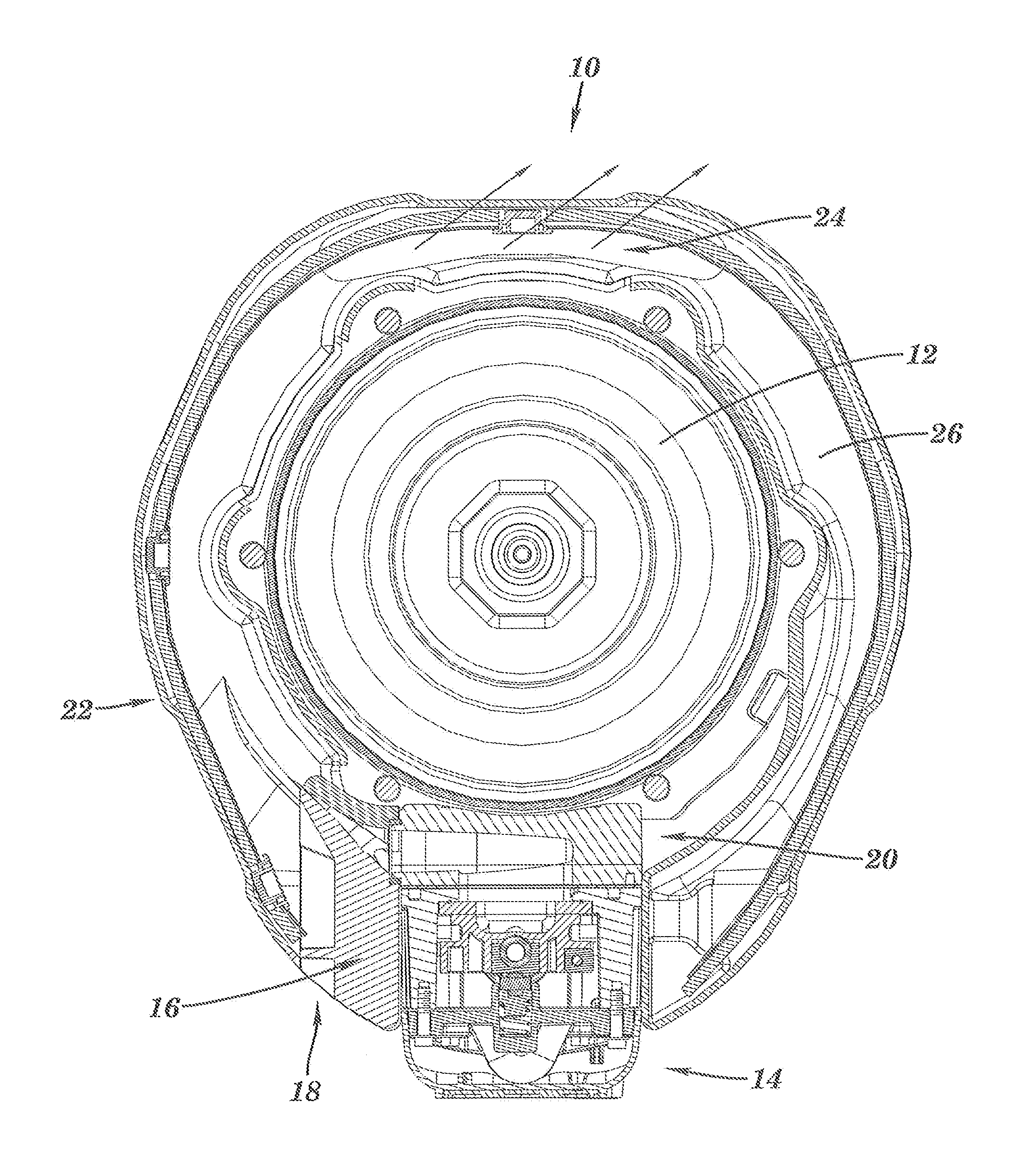
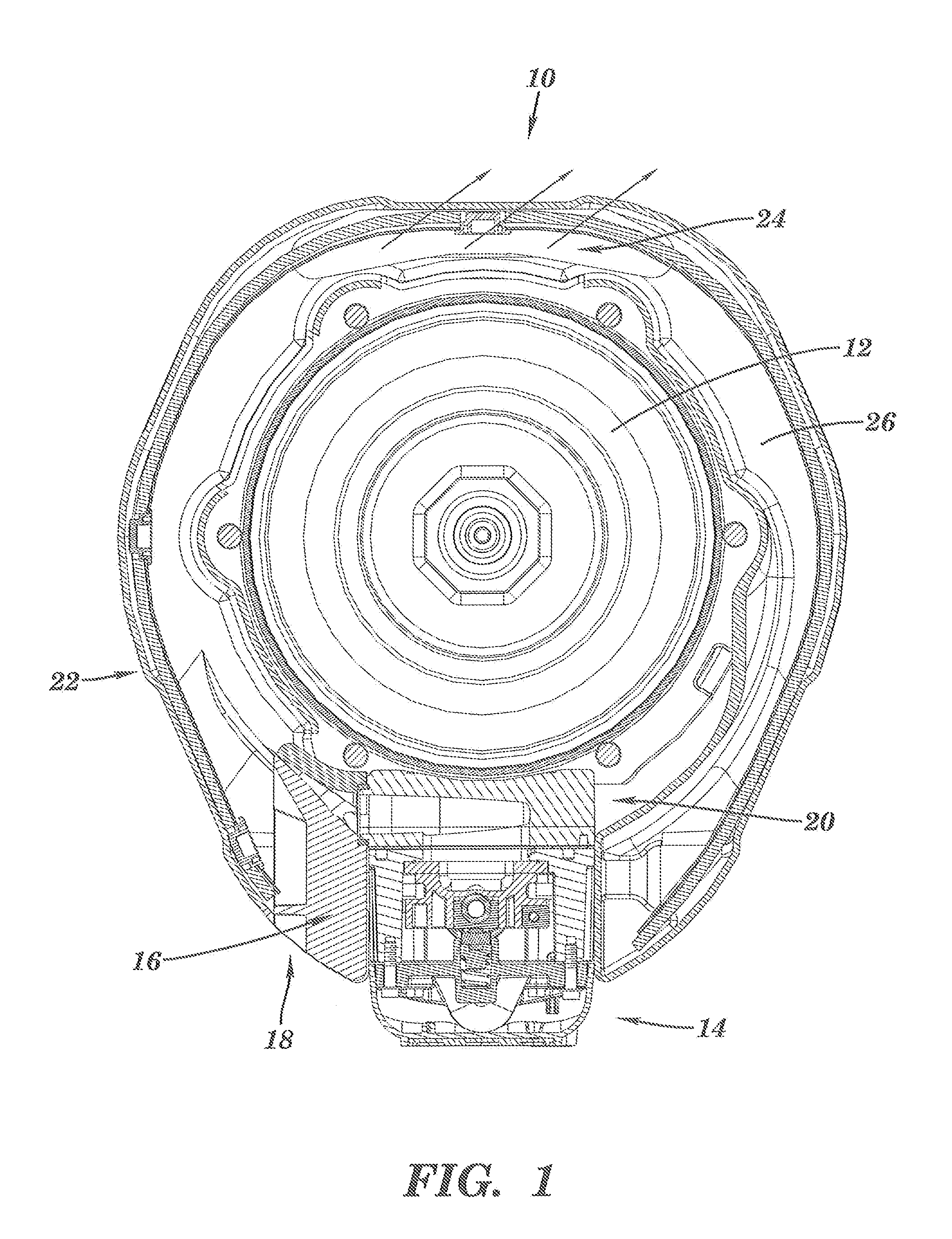
[0009]The air motor 10 of the instant invention has a piston 12 and an air valve 14. The induction exhaust has an exhaust manifold 16 and a muffler 22. In the instant invention, warm ambient air is drawn into the muffler 22. Heat from this external source is conducted through the finned manifold 16 to melt ice that can form inside the manifold 16 during the exhaust cycle.

[0010]The exhaust manifold 16 directs the exhaust air stream into the muffler 22 such that it creates a thin high velocity air stream creating a low pressure region on both sides of the stream due to the Bernoulli effect. This low pressure region creates a pressure differential which draws the warm external air into the exhaust system. The more external air that is drawn in, the more that icing will be reduced. This requires minimizing downstream exhaust pressure.

[0011]Minimizing downstream exhaust pressure, however, can lead to higher noise levels. In order to reduce noise, a reverberation chamber 26 is added after...


PUM


Abstract

The induction exhaust has an exhaust manifold 16 and a muffler 22. In the instant invention, warm ambient air is drawn into the muffler 22. Heat from this external source is conducted through the finned manifold 16 to melt ice that can form inside the manifold 16 during the exhaust cycle. The exhaust manifold 16 bolts to the side of the air motor air valve 14 and serves to direct, muffle and diffuse the air motor exhaust using a deflection plate, a diffraction plate and an expansion chamber is provided in the manifold to direct the exhaust out of the air valve and down the center of the muffler 22.

Description

TECHNICAL FIELD[0001]This application claims the benefit of U.S. application Ser. No. 60 / 820,405, filed Jul. 26, 2006.BACKGROUND ART[0002]While reciprocating air motors are well suited for operating reciprocating piston pumps, they can at times suffer from exhaust noise and a tendency to have ice build up in the air valve and / or exhaust passages due to the rapid expansion of the exhaust. U.S. Pat. No. 4,921,408 is one such attempt to improve operation and the contents thereof are incorporated by reference.DISCLOSURE OF THE INVENTION[0003]The induction exhaust has an exhaust manifold and a muffler. In the instant invention, warm ambient air is drawn into the muffler. Heat from this external source is conducted through the finned manifold to melt ice that can form inside the manifold during the exhaust cycle.[0004]The exhaust manifold directs the exhaust air stream into the muffler such that it creates a thin high velocity air stream creating a low pressure region on both sides of the...

Claims


Application Information

Patent Timeline
Patent Type & Authority Applications(United States)
IPC IPC(8): F01N5/02F01N1/02
CPCF01N13/10F01B31/02F04B53/00F04B39/00
Inventor BEHRENS, DAVID M.BAUCK, MARK L.HOLMAN, JOHN C.WEINBERGER, MARK T.ROSS, DANIEL P.
Owner BEHRENS DAVID M
Why Eureka
Try Eureka