LED device and LED driver

a technology of led driver and led device, which is applied in the direction of electric variable regulation, process and machine control, instruments, etc., can solve the problems of reliability decline, normal operation cannot be performed, and the power consumption of the constant current driving circuit is higher, so as to achieve suppressed or reduced the power consumption ensure stable and normal operation of the constant current driving circuit.

Active Publication Date: 2009-11-26
TEXAS INSTR INC
View PDF6 Cites 101 Cited by
  • Summary
  • Abstract
  • Description
  • Claims
  • Application Information

AI Technical Summary

Benefits of technology

[0013]An objective of the present invention is to solve the aforementioned problems of the prior art by providing an LED driver and an LED device characterized by the fact that when the LED is driven to emit light, the power consumption generated in the constant current driving circuit is suppressed or reduced, while stable and normal operation of the constant current driving circuit can be guaranteed.

Problems solved by technology

Consequently, the higher the headroom voltage HVy, the higher the power consumption of the constant current driving circuit.
In addition, when the overall power consumption (heat generation quantity) of LED driver IC 14(x) is over the permissible loss of the IC package, the driver circuit is broken or malfunctions so that normal operation cannot be performed, and the reliability falls.

Method used


Image

  • LED device and LED driver
  • LED device and LED driver
  • LED device and LED driver

Examples


Embodiment Construction

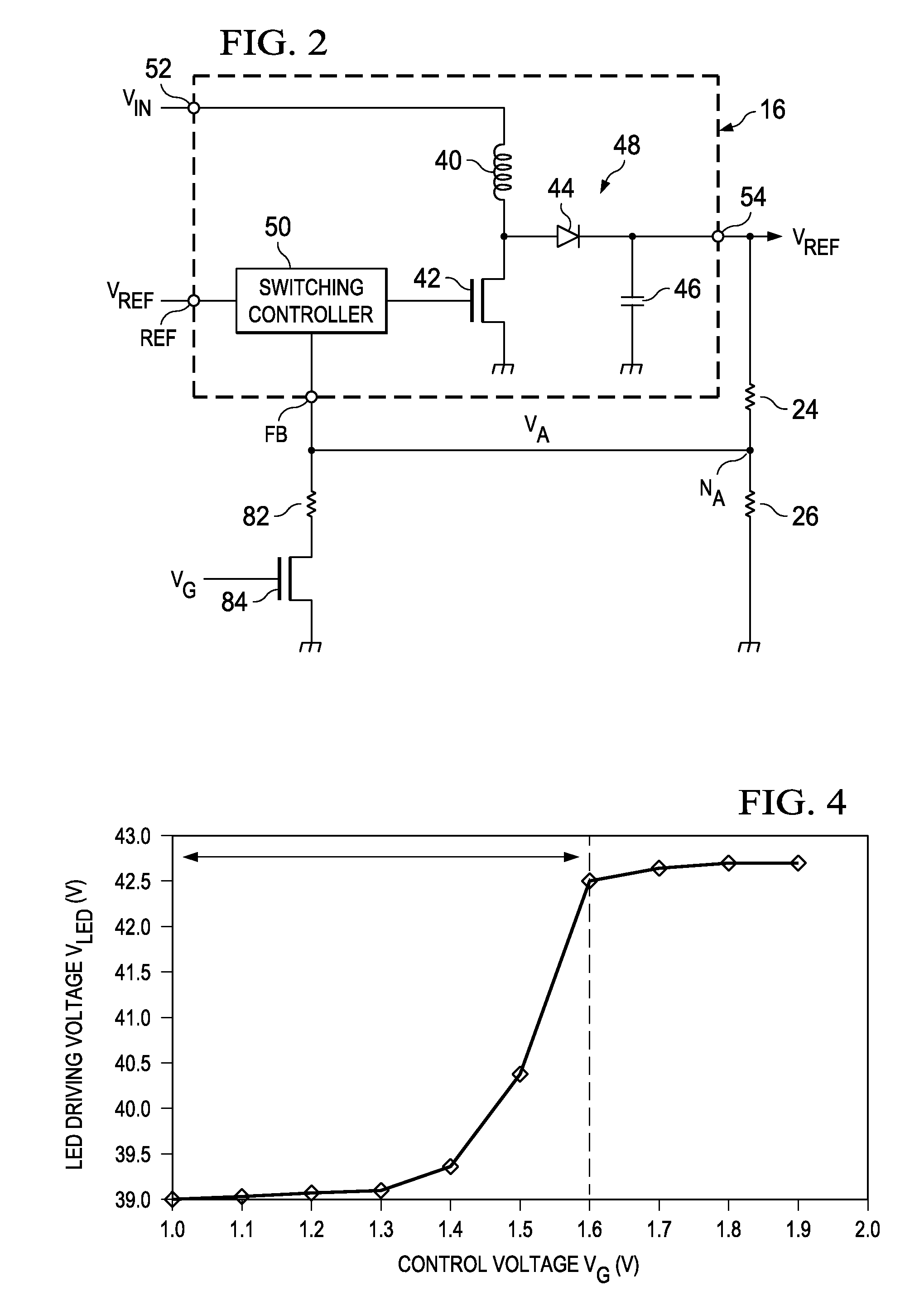
[0037]According to an aspect of the LED device and LED driver of the present invention with said constitution and operation, while the power consumption generated in the constant current driving circuit in light emission driving of LEDs is suppressed or reduced, stable or normal operation of the constant current driving circuit can be guaranteed.

[0038]In the following, an explanation will be given regarding an embodiment of the present invention with reference to FIGS. 1-10.

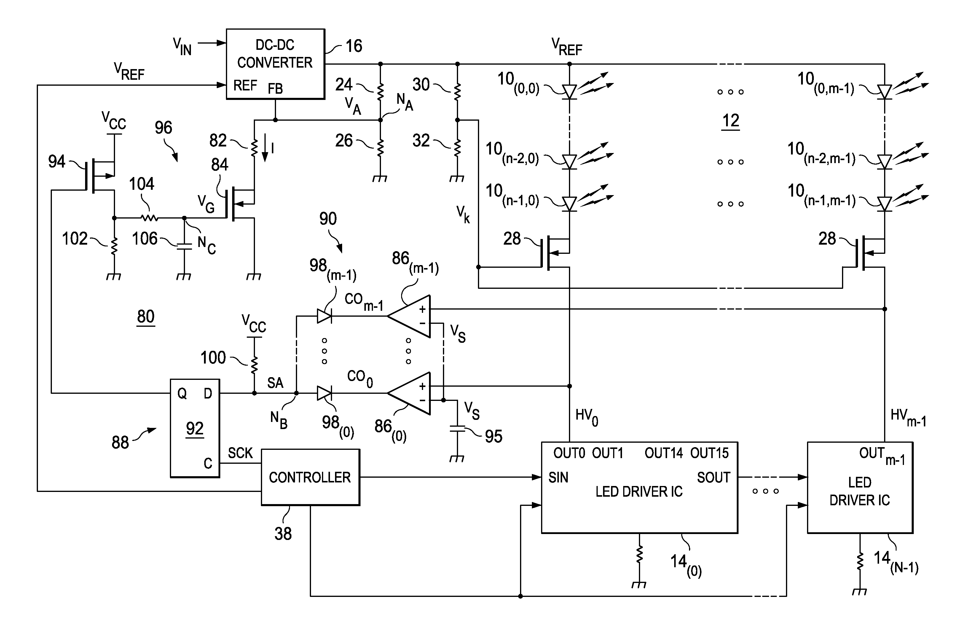
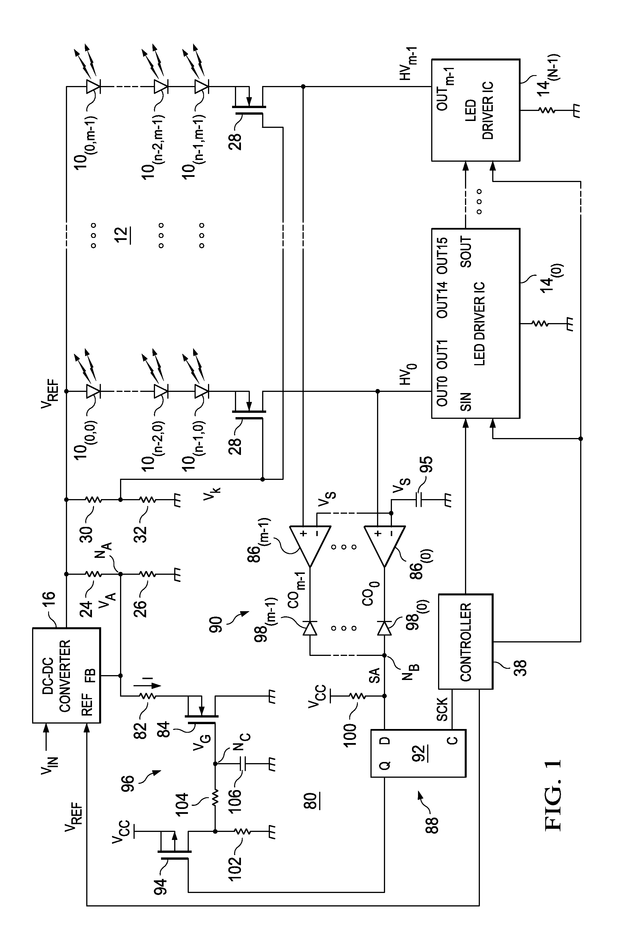
[0039]FIG. 1 is a diagram illustrating the circuit constitution of an LED device having an LED driver in an embodiment of the present invention. This LED device, for example, can be used in the LED backlight for an LCD-TV unit. In this figure, the same symbols as those used above in the prior art shown in FIG. 11 are adopted. errata

[0040]The principal constitution of this LED device is similar to that of the LED device in the prior art (FIG. 11). It has LED array 12 consisting of n×m LEDs (10(0,0), . . . 10(n-2,0...


PUM

PropertyMeasurementUnit
DC voltageaaaaaaaaaa
frequencyaaaaaaaaaa

Abstract

A LED device having a LED array, LED driver ICs, DC-DC converter, a first feedback circuit consisting of voltage dividing resistors, and a headroom voltage monitoring circuit having controller and second feedback circuit. In second feedback circuit, headroom voltages obtained at output current terminals of the LED driver ICs, are fed back to DC-DC converter.

Description

FIELD OF THE INVENTION[0001]The present invention pertains to an LED device that can be used in backlighting, illumination, displays, etc., and an LED driver for driving said LED to emit light.BACKGROUND OF THE INVENTION[0002]At present, LEDs (light-emitting diodes) of various types, such as those with high luminance of light emission, and those emitting white light and various colors of light have been developed and are in mass production, and have found wide application in various fields, such as backlighting, illumination, displays, etc.[0003]FIG. 11 is a diagram illustrating the circuit constitution of a conventional LCD device in the prior art for use as a backlight in LCD (liquid crystal display)-TV (television) applications. As shown in the figure, this LCD device has LED array 12 consisting of n×m LEDs (10(0,0), . . . 10(n-2,0), 10(N-1,0))-(10(0,m-1), . . . 10(n-2,m-1), 10(N-1,m-1)) (where n and m are integers of 2 or more) and one or a plurality (N) of LED driver ICs (integ...

Claims


Application Information

Patent Timeline
Patent Type & Authority Applications(United States)
IPC IPC(8): H05B37/02G02F1/133H01L33/00
CPCH05B33/0827H05B45/347H05B45/3725H05B45/46
Inventor TANAKA, SHINICHINARISAWA, KIYOSHI
Owner TEXAS INSTR INC
Why Eureka
Try Eureka