Biometric authentication system, authentication client terminal, and biometric authentication method

a biometric authentication and client terminal technology, applied in the field of biometric authentication systems, can solve the problems of malicious users, no logical guarantee for minimizing the expected value of the number of inputs of biometric data necessary for determination, etc., and achieve the effect of improving the expected value of reducing the number of inputs

Active Publication Date: 2009-11-26
HITACHI LTD
View PDF58 Cites 41 Cited by
  • Summary
  • Abstract
  • Description
  • Claims
  • Application Information

AI Technical Summary

Benefits of technology

[0013]In the technology disclosed in the Noda, the determination is made by comparing the likelihood ratios with the threshold each time the feature is acquired, in order to aim at reducing the number of inputs of the biometric data necessary for authentication. However, the method of biometric identification that calculates likelihood ratios from the feature distribution and compares the obtained likelihood ratios with the threshold, provides no logical guarantee for minimizing the expected value of the number of inputs of the biometric data necessary for determination. In other words, the technology of the Noda has left room for improvement in reduction of the expected value of the number of inputs of the biometric data necessary for authentication.

Problems solved by technology

However, the method of biometric identification that calculates likelihood ratios from the feature distribution and compares the obtained likelihood ratios with the threshold, provides no logical guarantee for minimizing the expected value of the number of inputs of the biometric data necessary for determination.
Further, in conventional biometric identification systems, there is a problem that a malicious user, who has not been registered, attempts authentication over and over again to be successful in forgery.

Method used


Image

  • Biometric authentication system, authentication client terminal, and biometric authentication method
  • Biometric authentication system, authentication client terminal, and biometric authentication method
  • Biometric authentication system, authentication client terminal, and biometric authentication method

Examples


first embodiment

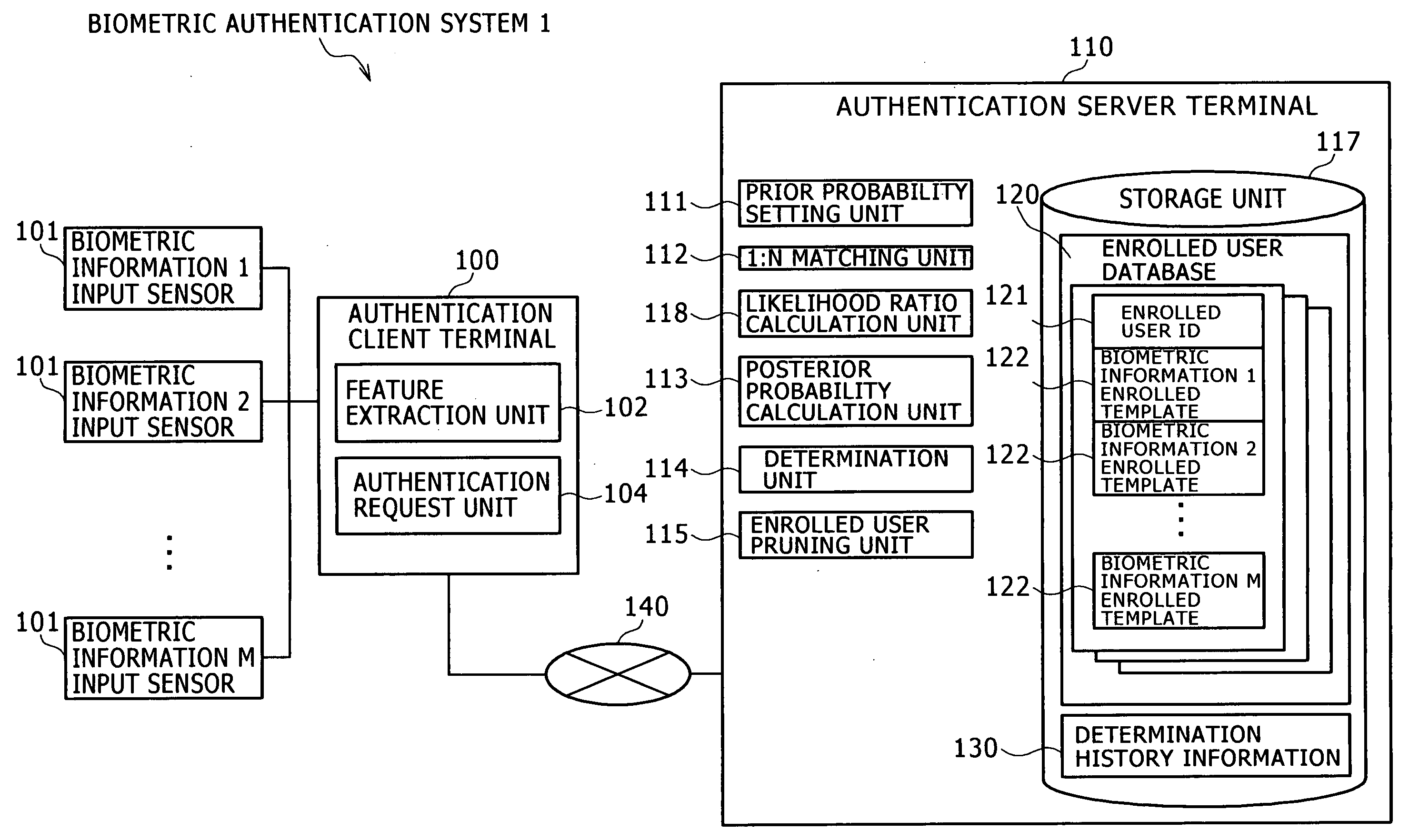
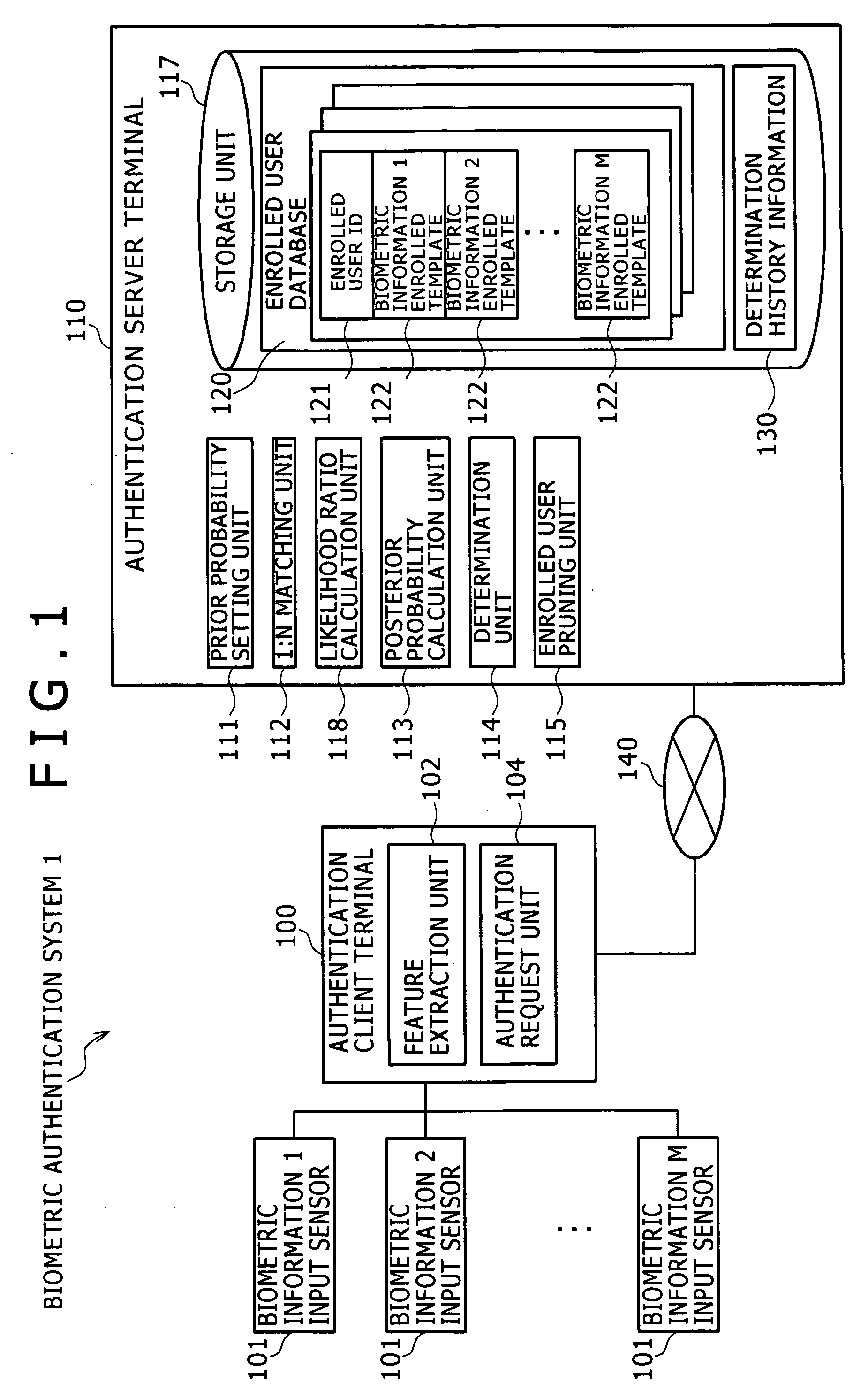
[0046]A biometric authentication system 1 of this embodiment is a biometric authentication system that performs biometric identification between a claimant v and N enrolled users un (n=1 to N), using plural biometric data. The claimant is a user to be identified through an authentication client terminal 100. The enrolled user is a user whose feature data of the biometric data is previously registered for the purpose of matching.

[0047]FIG. 1 shows an example of the configuration of the biometric authentication system 1. The biometric authentication system 1 includes the authentication client terminal 100 and an authentication server terminal 110. The authentication client terminal 100 acquires the feature data from the biometric data of the claimant v, and presents the information such as the authentication result to the claimant v. The authentication server 110 performs biometric identification or other processing. The authentication client terminal 100 and the authentication server...

second embodiment

[0114]In this embodiment, authentication is performed using plural different types of biometric information belonging to the same modality. The second embodiment will be described below focusing on the difference from the first embodiment.

[0115]In step S307 of FIG. 3, the 1:N matching unit 112 of the authentication server terminal 110 performs 1:N matching between the claimant feature data extracted by the feature extraction unit 102 of the authentication client terminal 100, and M enrolled templates 122 held in the enrolled user database 120 with respect to each of N enrolled users un. Then, the 1:N matching unit 112 calculates the matching score sjnm of the m-th enrolled template with respect to each of the enrolled users un. In the following description, the distance in the feature space is used as the method for calculating matching scores. In this case, the smaller the matching score the better. In other words, the smaller the matching score, the more two biometric information ...

third embodiment

[0124]A biometric authentication system 2 of this embodiment is a cardless credit payment system. The third embodiment will be described below focusing on the difference from the first embodiment.

[0125]FIG. 7 shows an example of the configuration of the biometric authentication system 2.

[0126]A loss calculation unit 102a calculates a loss W1 occurring when v is a enrolled user and is identified as another enrolled user, and a loss W0 occurring when v is a non-enrolled user and is identified as a certain enrolled user, based on the price Q of a product the claimant v purchased.

[0127]A prior probability initial setting unit 111a initializes the posterior probabilities of the enrolled users un and the posterior probability of the non-enrolled user u0.

[0128]A prior probability and threshold setting unit 111b sets the prior probability of each of the enrolled users un and a corresponding threshold, as well as the prior probability of the non-enrolled user u0 and a corresponding threshold...


PUM


Abstract

A biometric authentication system, authentication client terminal, and biometric authentication method are provided to reduce an expected value of the number of inputs of biometric data for authentication, while effectively preventing forgery. In a biometric authentication system, prior probabilities of enrolled users un and non-enrolled user u0 are previously set. 1:N matching is performed between feature data of a claimant v and matching feature data. The matching score is calculated for each enrolled user un. A ratio of the likelihood v=un to the likelihood v≠un is calculated for each enrolled user un using the calculated matching scores. Posterior probabilities of the enrolled users un and non-enrolled user u0 are calculated, using the likelihood ratios, and the prior probabilities of both the enrolled users un and the non-enrolled user u0. Then, determination is made by comparing each posterior probability with a first threshold.

Description

INCORPORATION BY REFERENCE[0001]This application claims priority based on Japanese patent applications, No. 2008-119131 filed on Apr. 30, 2008 and No. 2008-312411 filed on Dec. 8, 2008, the entire contents of which are incorporated herein by reference.BACKGROUND[0002]The present invention relates to a biometric authentication system using biometric information to verify identities.[0003]Biometric authentication is known as an authentication technology with advantages that the forgery of information input for authentication (for example, fingerprint) is more difficult than the authentication based on the password, IC card, or other identifying information, and that the information input for authentication is not forgotten.[0004]In the biometric authentication, biometric data is first acquired from a user, and information called the feature is extracted from the biometric data and is registered in advance. This registered information is called the enrolled template. The user who has b...

Claims


Application Information

Patent Timeline
Patent Type & Authority Applications(United States)
IPC IPC(8): G05B19/00G06F21/32
CPCG06K9/6277G06K9/00885G06V40/70G06V40/10G06F18/2415
Inventor MURAKAMI, TAKAOTAKAHASHI, KENTA
Owner HITACHI LTD
Why Eureka
Try Eureka