Liquid crystal display device
- Summary
- Abstract
- Description
- Claims
- Application Information
AI Technical Summary
Problems solved by technology
Method used
Image

Examples
first embodiment
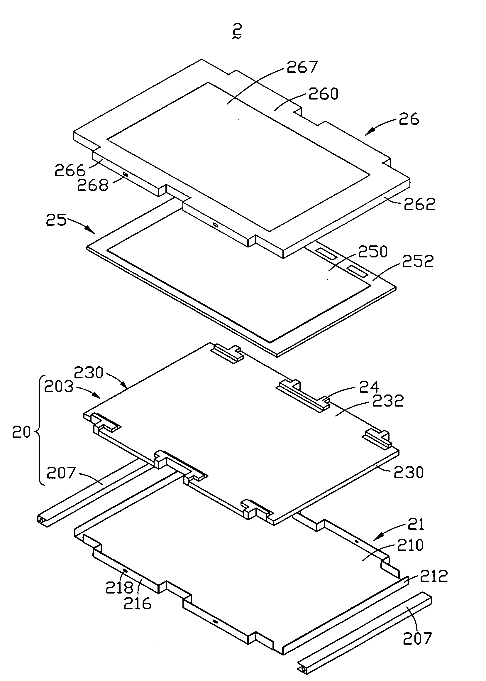
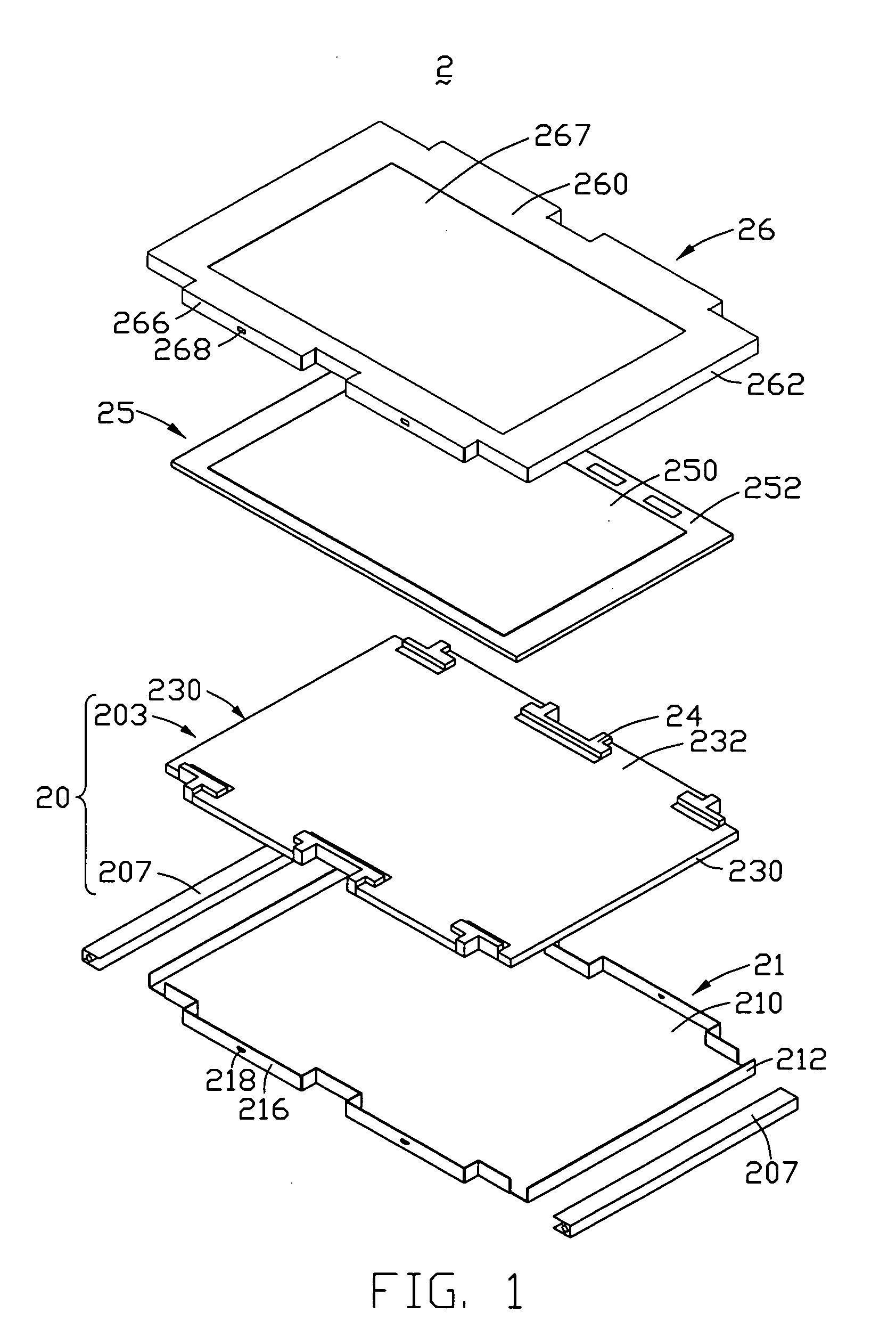
[0020]FIG. 1 is a schematic, exploded view of an LCD device according to the present disclosure. The LCD device 2 includes a backlight module 20, a bottom tray 21, a plurality of blocks 24, a liquid crystal panel 25, and a bezel 26. The bottom tray 21 engages the bezel 26 to accommodate the backlight module 20 and the liquid crystal panel 25.
[0021]The bottom tray 21 includes a bottom plate 210, and two first sidewalls 212 opposite to each other, and two second sidewalls 216 opposite to each other. The four sidewalls 212, 216 extend perpendicularly from edges of the bottom plate 210. Each of the two first sidewalls 212 has a concavo-convex shape, and each includes two first protrusions 218. The top plate defines a window 267 to expose the liquid crystal panel 25. The bottom tray 21 is made from iron, aluminum (Al), or an alloy containing iron and Al.
[0022]The bezel 26 includes a top plate 260, two opposite third sidewalls 262, and two opposite fourth sidewalls 266. The four sidewalls...
second embodiment
[0027]FIG. 6 shows an LCD device according to the present disclosure, differing from LCD device 2 only in that a second sidewall 316 of a bottom tray is straight, such that the blocks 34 include no extending portions, allowing the bottom tray to be molded more easily.
third embodiment
[0028]FIG. 7 shows an LCD device according to the present disclosure, differing from LCD device 2 only in that, here, LCD device 4 includes a box 41 to replace the bottom tray 21 and the bezel 26, in which an assembly including a backlight module and a liquid crystal panel is received from one side. Manufacture is thus simplified.
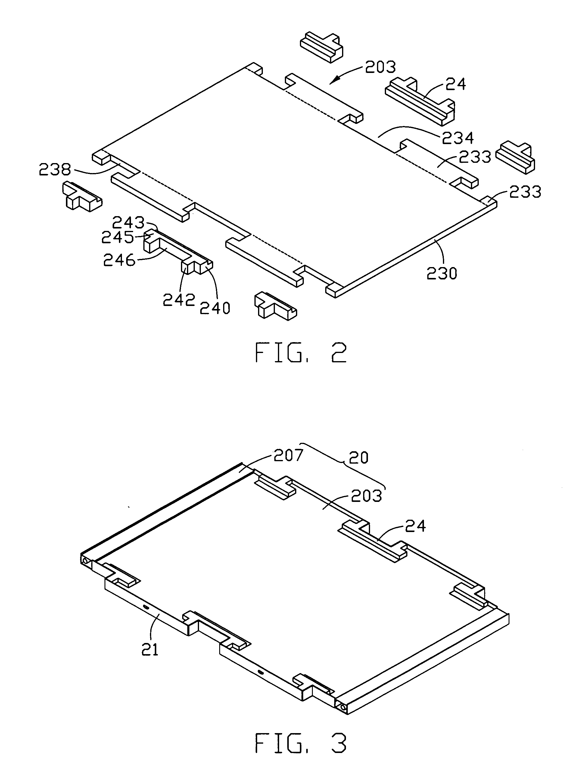
[0029]In further and / or alternative embodiments, the LCD device 2 may further include an optical assembly disposed between the liquid crystal panel 25 and the light guide plate 203, with the surface of the first step 243 higher than that of the light guide plate 203. Moreover, the blocks 24 and the light guide plate 203 may be molded as a one-piece member.
PUM
 Abstract
Description
Claims
Application Information
 - R&D Engineer
- R&D Manager
- IP Professional
- Industry Leading Data Capabilities
- Powerful AI technology
- Patent DNA Extraction
Browse by: Latest US Patents, China's latest patents, Technical Efficacy Thesaurus, Application Domain, Technology Topic.
© 2024 PatSnap. All rights reserved.Legal|Privacy policy|Modern Slavery Act Transparency Statement|Sitemap