UV Sterilizer for Fluid of Large Flow Rate

a technology of uv sterilization and fluid, which is applied in the direction of chemical/physical/physical-chemical processes, chemical apparatus and processes, energy-based chemical/physical/physical-chemical processes, etc., can solve the problems of short circuit of fluid flow around, shorten the distance that fluid travels, and reduce the amount of uv radiation applied to the fluid, so as to improve the utilization of uv light, improve the pressure resistance, and reduce the cost of the system

Inactive Publication Date: 2009-11-26
FUJIAN NEWLAND ENTECH CO LTD
View PDF3 Cites 5 Cited by
  • Summary
  • Abstract
  • Description
  • Claims
  • Application Information

AI Technical Summary

Benefits of technology

[0014]3. Due to the use of the baffle, the mounting part may be embodied in a duct with circular cross section, with fluid ports being provided on both ends of the duct, which ports can be shaped as rectangular, e.g. square, thus on one hand, improving the pressure resistance off the sterilization chamber and the safety of the fluid sterilization system, and on the other hand, improving the utilization of the UV light and reducing the cost of the system.
[0015]4. Since the fluid conduits may be connected by means of the mounting part(s) or the UV sterilizer(s), on the wall of which may be mounted at least one UV sterilization module, it is possible to select some of the mounting part(s) for the installation of at least one UV sterilization module as required, also it is possible to increase or decrease the number of the at least one UV sterilization module as required, thereby improving the sterilization effect and reducing the cost of the system.
[0016]5. Since the mounting part of the UV sterilize...

Problems solved by technology

Moreover, it is likely to create a short circuit of fluid flow around the wall of the cylinder when a large flow rate of fluid is involved.
That is, part of the fluid flow close to the cylinder wall directly flows out of the chamber without being sufficiently sterilized, which shortens the distance that fluid travels when being subjected to UV ...

Method used


Image

  • UV Sterilizer for Fluid of Large Flow Rate
  • UV Sterilizer for Fluid of Large Flow Rate
  • UV Sterilizer for Fluid of Large Flow Rate

Examples


Embodiment Construction

[0032]In the following one embodiment of the present invention will be described in detail with reference to the drawings.

[0033]In this context, the term “number” means one or an integral greater than one.

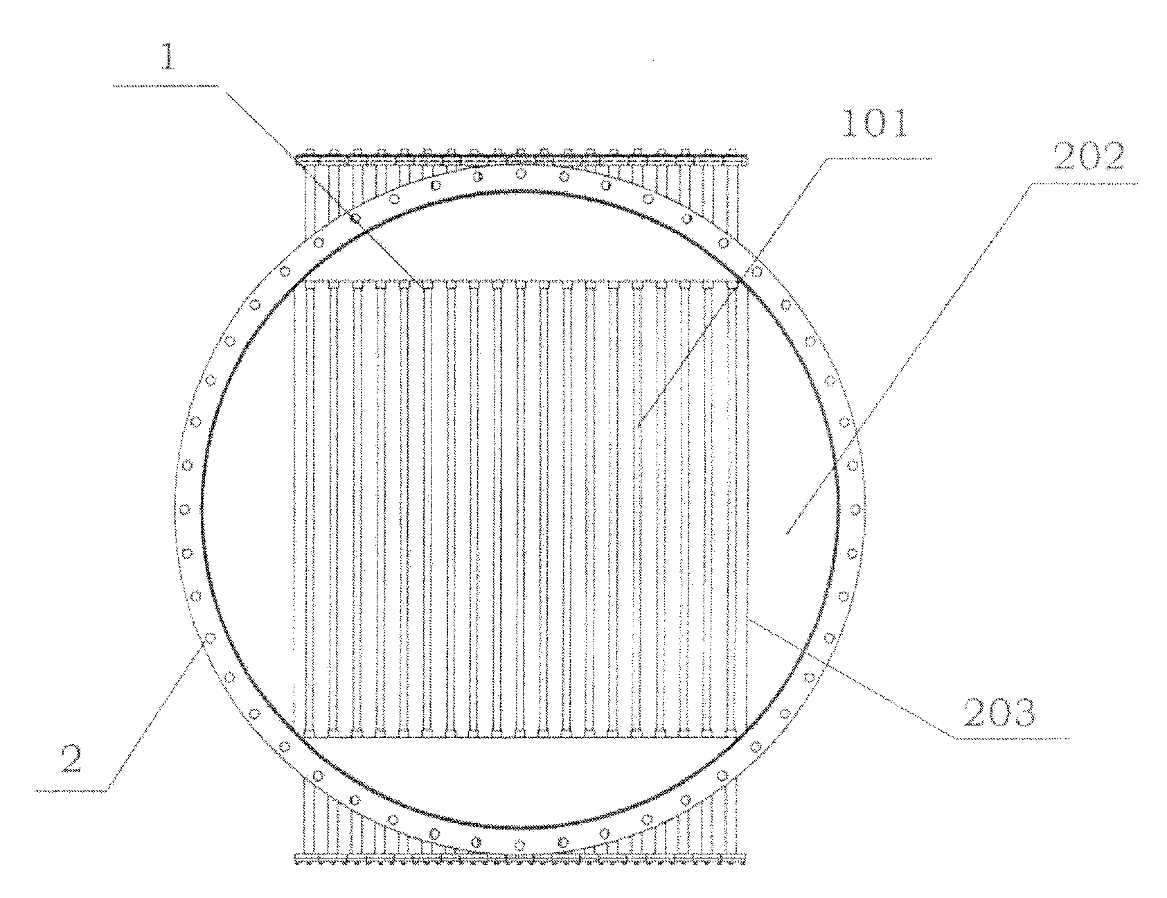
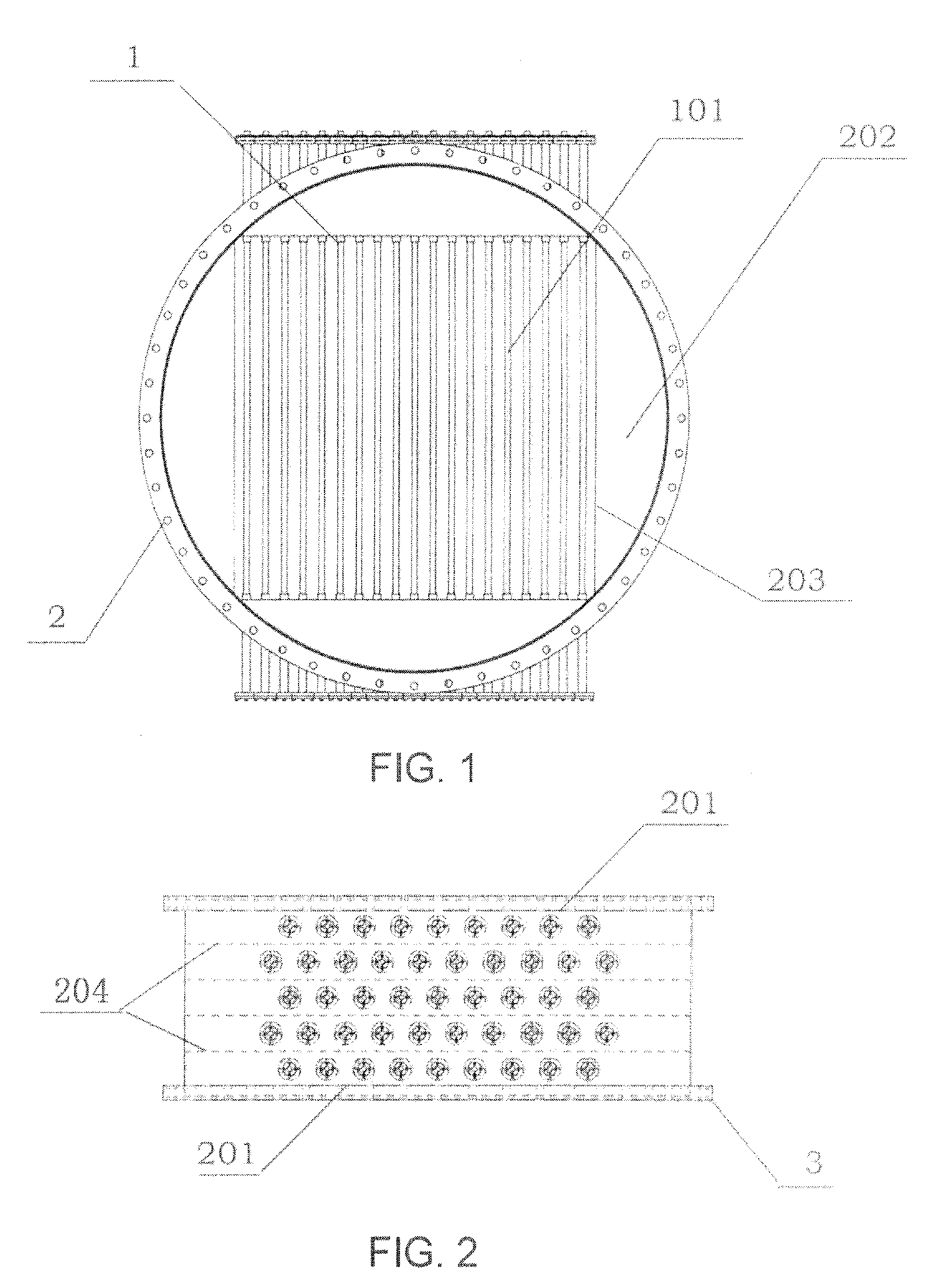
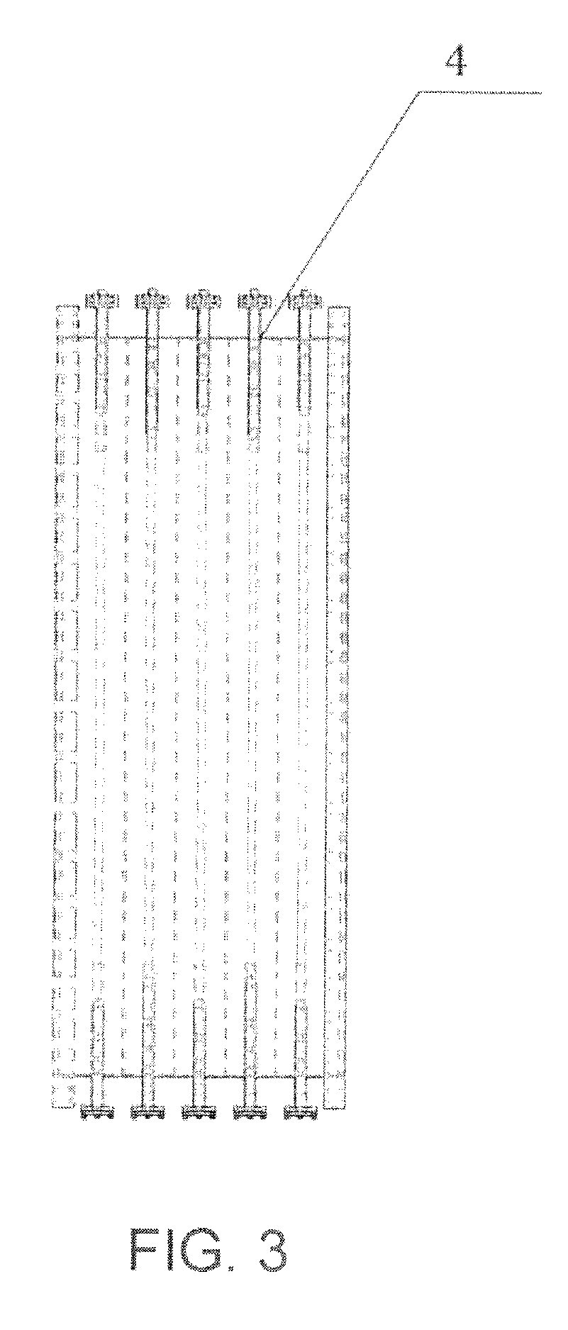
[0034]A UV sterilizer for fluid of large flow rate as shown in FIGS. 1, 2 and 3 employs modular design, which comprises at least one UV sterilization module 1 and a mounting part 2 for the same. Each UV sterilization module 1 comprises at least one UV lamp tube 101, and the mounting part 2 comprises a body in the form of a duct for the passage of fluid to be sterilized therethrough. A number of mounting apertures 4 for the UV sterilization module are provided on the wall of the duct, and on one or both end surfaces 201 of the duct are provided a baffle 202 extending from the outer peripheral of the one or both end surfaces 201 towards the center thereof. There is also a port 203 for the passage of fluid to be sterilized therethrough on said one or both end surfaces with the baffle ...


PUM


Abstract

A UV sterilizer for fluid of large flow rate comprises at least one U V sterilization module and an mounting part for said module, each module comprising at least one UV lamp tube, said mounting part comprising a body in the form of a duct for the passage of fluid to be sterilized therethrough, with a number of mounting apertures for the UV sterilization module being provided on the wall of the duct, and on one or both end surfaces of the duct there being provided a baffle extending from the outer peripheral of said one or both end surfaces towards the center thereof, with a port being left on said one or both end surfaces with the baffle for the passage of fluid to be sterilized therethrough. The UV sterilizer for fluid of large flow rate of the present invention may be widely used in water supply plant, pharmaceutical plant, food plant, drink plant, or other plants or sites where fluid need to be sterilized.

Description

CROSS-REFERENCE TO A RELATED APPLICATION[0001]This application claims priority to Chinese patent Application No. 200810071135.1, filed May 26, 2008, which is incorporated herein by reference in its entirety.FIELD OF THE INVENTION[0002]The invention generally relates to ultraviolet (UV) sterilization for fluid, and more particularly to a UV sterilizer for fluid of large flow rate.DESCRIPTION OF RELATED ART[0003]According to the prior art, a UV sterilizer of closed type usually has a main chamber of cylinder shape, with fluid inlets and outlets being provided on the wall of the cylinder and UV lamps being connected to the ends of the cylinder. Fluid flows into the chamber via the inlets, and flows out via the outlets after being subjected to UV radiation. Since the fluid inlets and outlets, which are respectively connected to the supply conduit and the discharge conduit, are provided on the wall of the cylinder for the inflow and outflow of the fluid, the flow pressure on said wall is...

Claims


Application Information

Patent Timeline
IPC IPC(8): B01J19/08
CPCC02F1/325C02F2201/328C02F2201/3227
Inventor CHEN, JIANHAN, MINYI
Owner FUJIAN NEWLAND ENTECH CO LTD
Why Eureka
Try Eureka