Mold Assembly

a technology of mold assembly and molded parts, which is applied in the field of mold assembly, can solve the problems of easy generation of strain inside the molded article, insufficient heat generation, and breakdown of electrically conductive layers, and achieves the effect of easy generation of strain and easy appearance failur

Inactive Publication Date: 2009-11-26
MITSUBISHI ENG PLASTICS CORP
View PDF5 Cites 15 Cited by
  • Summary
  • Abstract
  • Description
  • Claims
  • Application Information

AI Technical Summary

Benefits of technology

[0009]In the techniques disclosed in these Laid-Open patent publications, when the application of an electric current to the electrically conductive layer, etc., is stopped, the electrically conductive layer, etc., is instantly started to be cooled since only the thin electric-resistance layer is formed between the cavity surface of the mold made of a metal and the electri

Problems solved by technology

There are consequently involved problems that the molten thermoplastic resin injected into the cavity is rapidly cooled, to easily cause appearance failures such as a weld mark, a flow mark, etc., on a molded article and that a solidification layer is formed in the molten thermoplastic resin to easily generate a strain inside the molded article.
In a method in which an electric-resistance layer having a low electric-resistance value is formed, a low voltage is used, so that sufficient heat may not be generated depending upon a design of the electric-resistance layer used.
It is the

Method used


Image

  • Mold Assembly
  • Mold Assembly
  • Mold Assembly

Examples


example 1

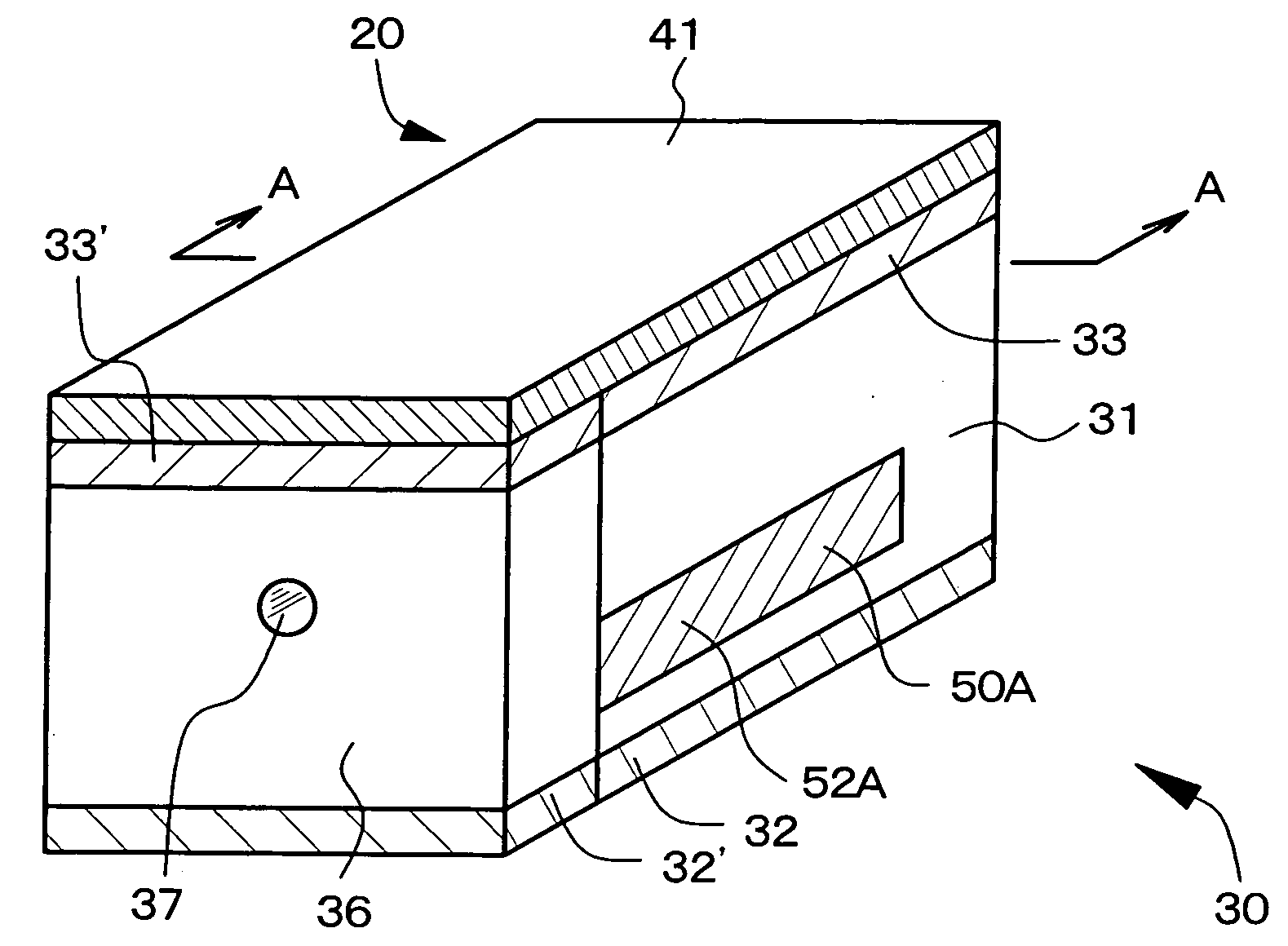
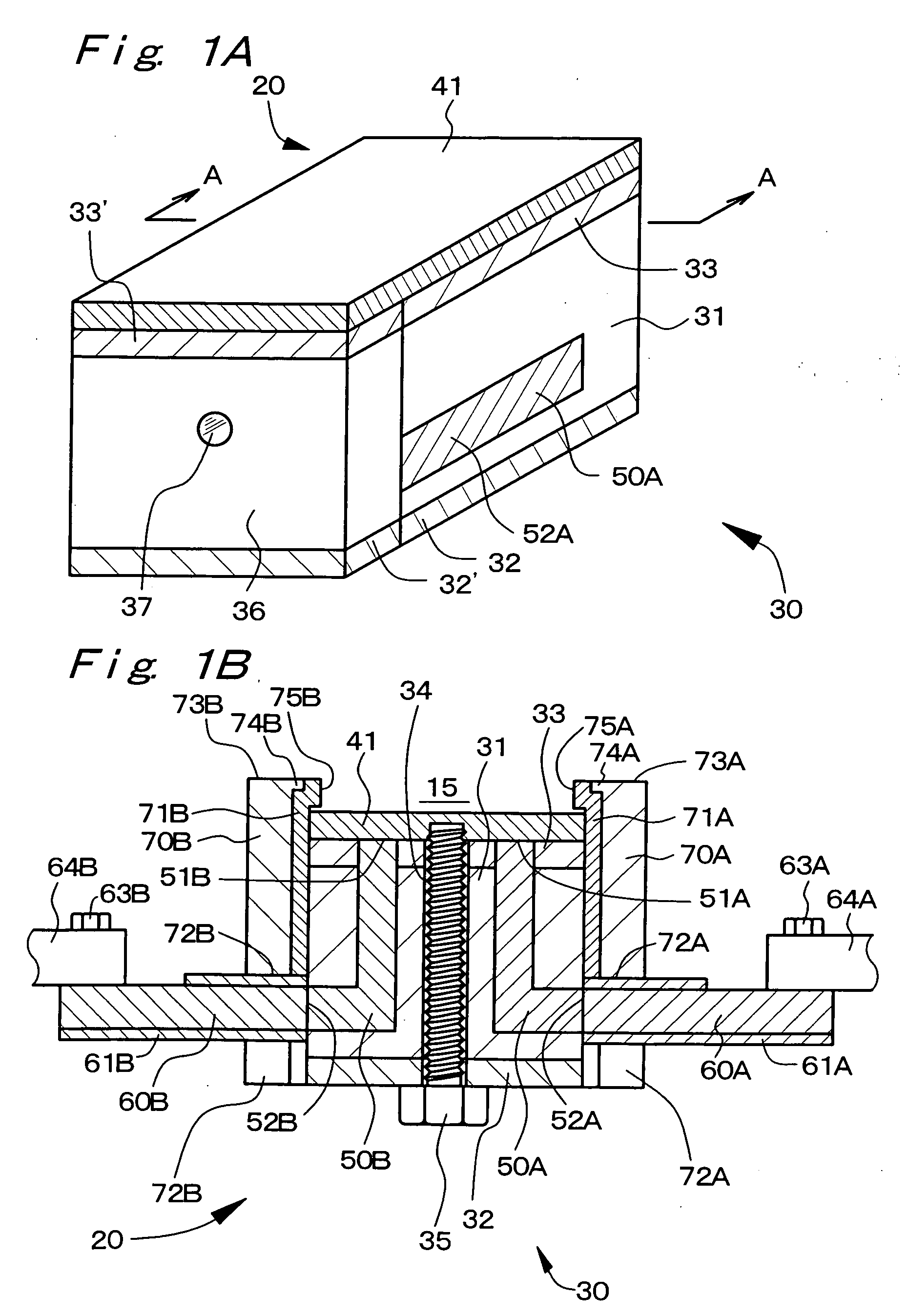
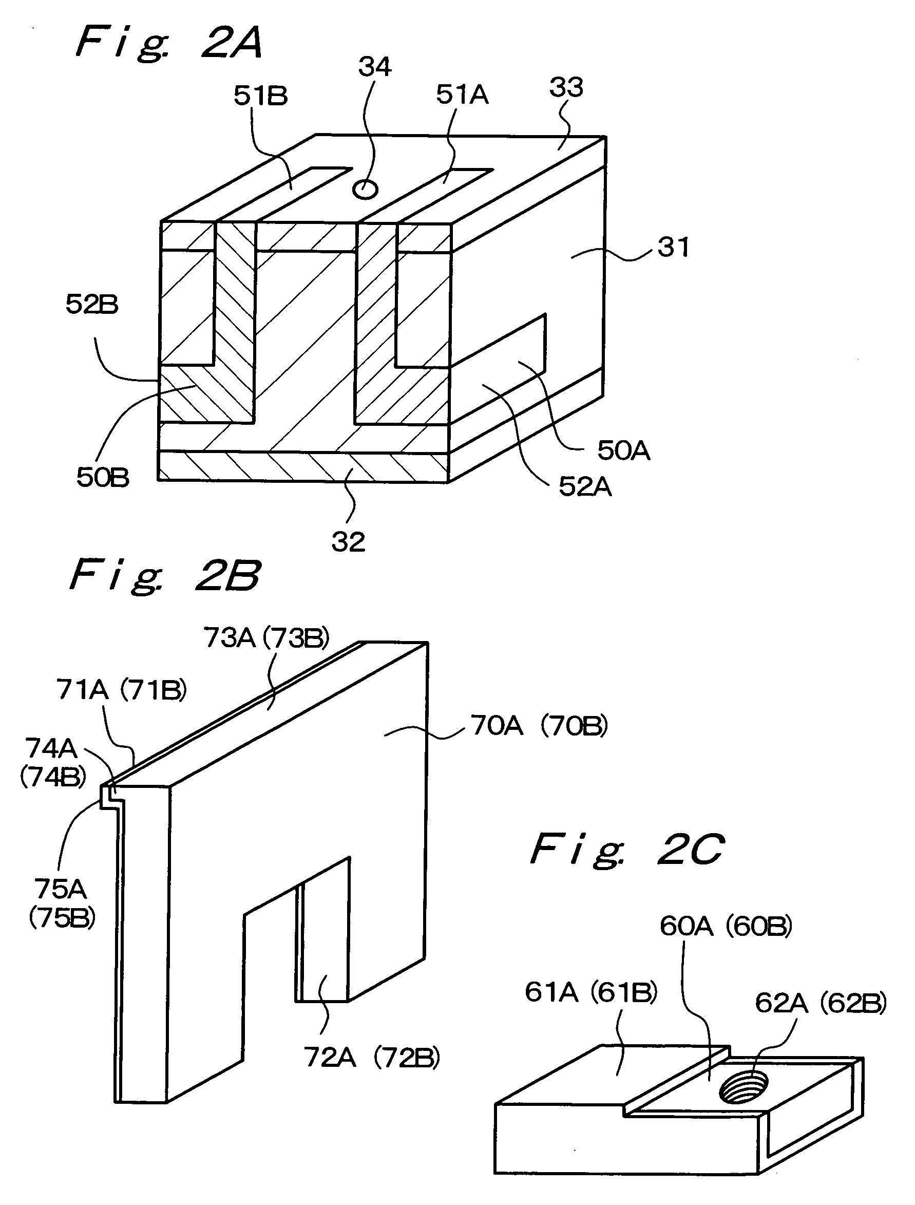
[0177]Example 1 relates to the mold assembly according to the first aspect of the present invention, more specifically, it relates to the mold assembly of the first constitution. FIG. 1(A) shows a schematic perspective view of an insert block assembly in the mold assembly of Example 1, and FIG. 1(B) shows a schematic cross-sectional view taken along arrows A-A in FIG. 1(A). FIG. 2(A) shows a schematic perspective view when the insert-block body, etc., are cut along arrows A-A in FIG. 1(A), FIG. 2(B) shows a schematic perspective view of a side block, and FIG. 2(C) shows a schematic perspective view of a first electrode and a second electrode. Further, FIG. 3 shows a perspective view of the insert-block body, etc., before they are assembled, and FIGS. 4(A) and 4(B) show conceptual views of the mold assembly and an injection molding apparatus as a whole. In FIG. 1(A), slanting lines are provided to some components for clearly showing components. FIG. 5, FIG. 6(A), FIG. 8, FIG. 9(A) an...

example 2

[0193]Example 2 is a variant of Example 1. In Example 2, as FIG. 5 shows a schematic cross-sectional view, a first conducting means 80A and a second conducting means 80B are formed of electrically conductive bolts (specifically, made of carbon steel) whose top end portions correspond to first end portions 81A and 81B, whose head portions correspond to second end portions 82A and 82B and which extend inside the insert block 30 (specifically, extend through the insert block 30 in Example 2) and are electrically insulated from the insert-block body 31. The top ends of the bolts are threadedly engaged with the heat-generating member 41 and the head portions of the bolts are in contact with the electrodes (not shown). That is, the second end portion 82A in the first conducting means 80A and the second end portion 82B in the second conducting means 80B are exposed in the bottom surface of the insert-block body 31. Since other components of the insert block assembly can be formed like the ...

example 3

[0194]Example 3 also relates to the mold assembly according to the first aspect of the present invention, and more specifically, it relates to the mold assembly of the second constitution. FIG. 6(A) shows a schematic cross-sectional view of an insert block assembly in a mold assembly of Example 3, and FIG. 6(B) shows a schematic perspective view obtained when an insert-block body is cut. Further, FIG. 7(A) schematically shows a pattern of a first conductive region, a conductive-region-extending area and a second conductive region in the mold assembly of Example 3.

[0195]The basic constitution and structure of the mold assembly in Example 3 are the same as the constitution and structure of the mold assembly explained in Example 1. And, an insert block 130 in Example 3 is constituted of the insert-block body 31 similar to that in Example 1 and the insulating layer 33 similar to that in Example 1. Further, the insert block 130 is constituted of a first conductive region 139A, a second c...


PUM

PropertyMeasurementUnit
Temperatureaaaaaaaaaa
Lengthaaaaaaaaaa
Lengthaaaaaaaaaa

Abstract

A mold assembly comprising a mold, an insert block assembly 20 having an insert block 30, and a first electrode 60A and a second electrode 60B, the insert block 30 comprises an insert-block body 31, and an insulating layer 33, the insert block assembly 20 further comprises a heat-generating member 41 that is electrically connected to the first electrode 60A and the second electrode 60B, that is fixed on the insulating layer 33, that constitutes part of the cavity 15 and that generates Joule heat.

Description

TECHNICAL FIELD[0001]The present invention relates to a mold assembly.BACKGROUND ART[0002]In recent years, in order to meet demands for a weight decrease and functional improvements of molded articles, a decrease in thickness and an increase in size are in progress with regard to molded articles. In particular, in an injection molding technique, it is required to cause a molten thermoplastic resin to flow in a thin cavity for shaping a molded article having a desired form, and various studies are hence under way as will be explained below.[0003]One of them is focused on a method in which the viscosity of a thermoplastic resin as a molding material is decreased to increase its flowability in a cavity. Specifically, an attempt is made to make a thin cavity filled by decreasing the molecular weight of a thermoplastic resin or increasing the resin temperature of a thermoplastic resin. However, when the molecular weight of a thermoplastic resin is decreased, a molded article may break du...

Claims


Application Information

Patent Timeline
IPC IPC(8): B29C45/73
CPCB29C33/02B29C35/02B29C2045/7393B29C45/73B29C2033/023B29C45/2673B29C45/14
Inventor KAYANO, YOSHIHIROTAHARA, HISASHI
Owner MITSUBISHI ENG PLASTICS CORP
Why Eureka
Try Eureka