
Valve timing adjustment device

a timing adjustment and valve technology, applied in valve details, valve arrangements, machines/engines, etc., can solve the problems of wear and unusual noise wear and unusual noise may arise at the meshing portion between the gear member and the planetary gear, and achieve the effect of easy loosing and easy strained

Active Publication Date: 2020-11-10
DENSO CORP
View PDF9 Cites 0 Cited by
  • Summary
  • Abstract
  • Description
  • Claims
  • Application Information

AI Technical Summary

Benefits of technology

The patent text discusses a problem in a valve timing adjustment device where the relative torque between the gear member and the cover member can cause the fastening member to become loose, resulting in wear and unusual noise. The patent aims to improve the durability and quietness of the device by addressing this problem. The technical effect of the patent is to enhance the durability and quietness of the valve timing adjustment device.

Problems solved by technology

As a result, the fastening member that axially fastens the gear member with the cover member may be easily loosened, so that wear and unusual noise may arise at the meshing portion between the gear member tilted due to the looseness and the planetary gear.
On the other hand, when the fastening torque caused by the fastening member is previously increased for inhibiting such looseness of the fastening member, the gear member may be easily strained, and also due to this strain, wear and unusual noise may arise at the meshing portion between the gear member and the planetary gear.

Method used


Image

  • Valve timing adjustment device
  • Valve timing adjustment device
  • Valve timing adjustment device

Examples


first embodiment

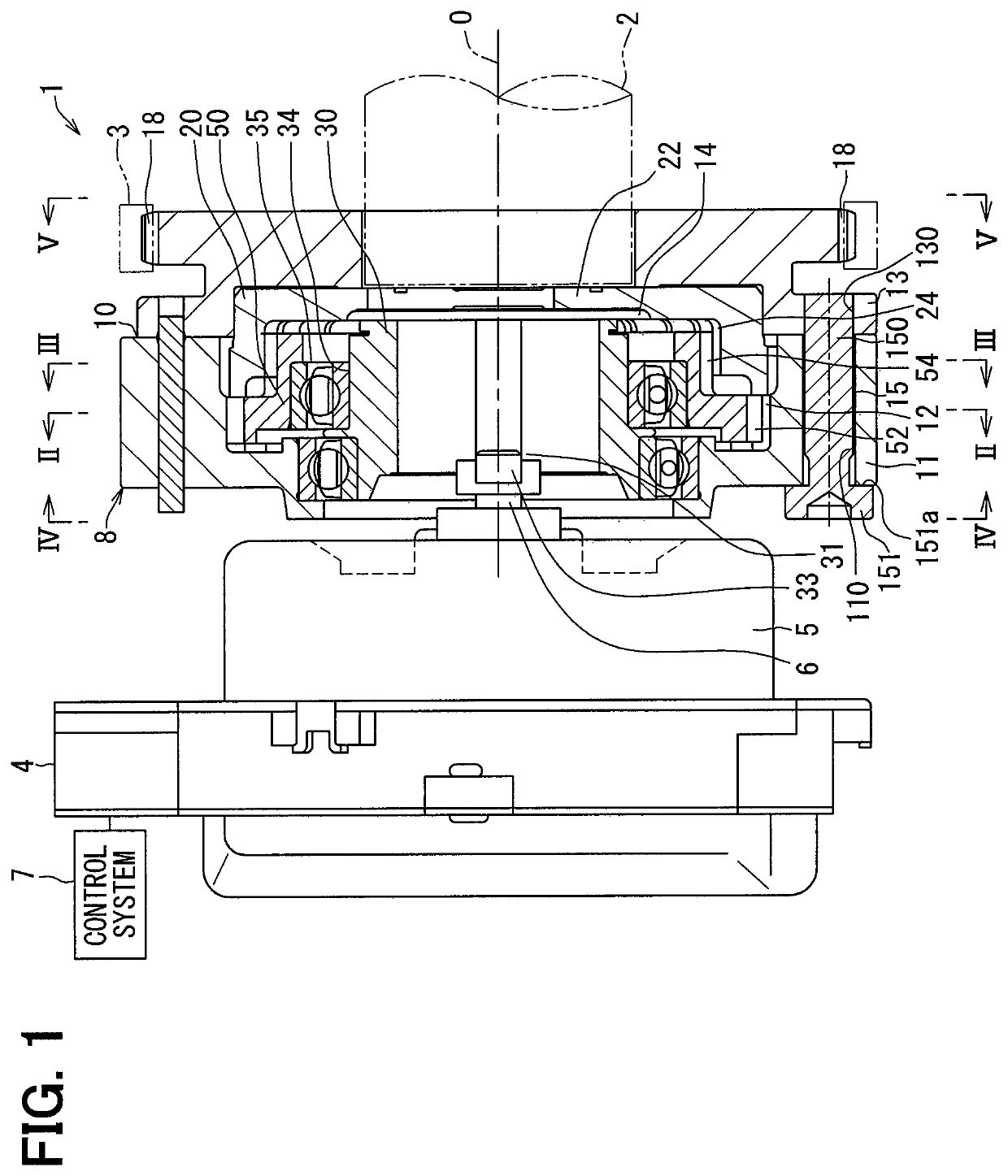
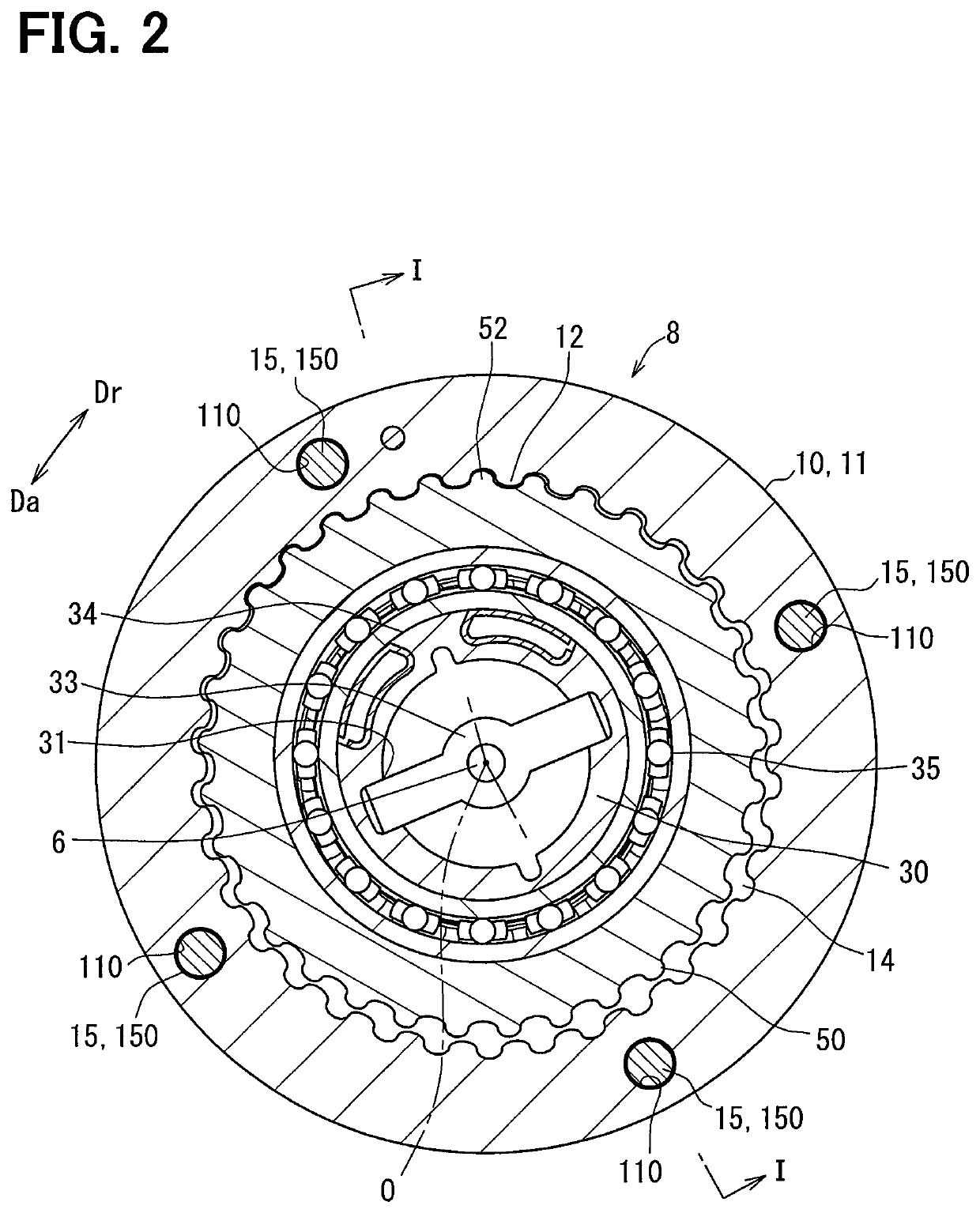
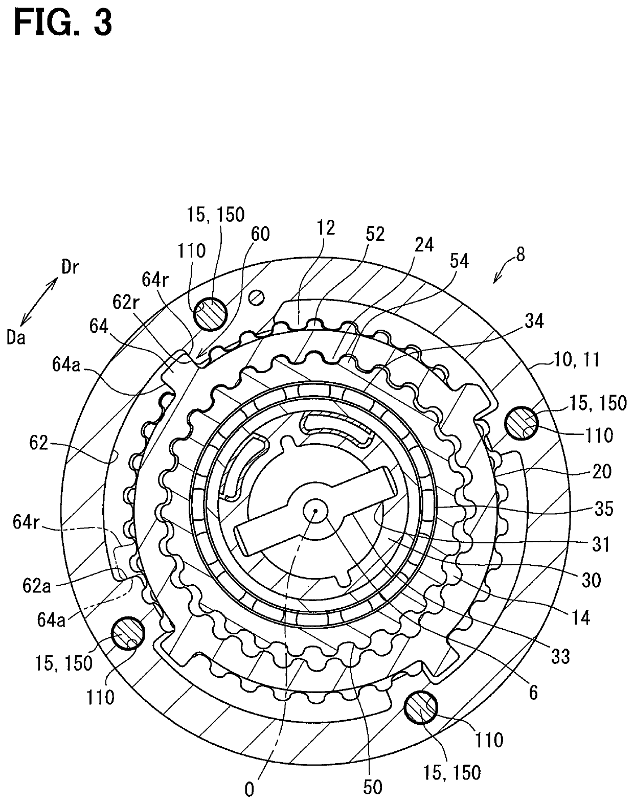
[0028]As shown in FIG. 1, a valve timing adjustment device 1 according to a first embodiment of the present disclosure is installed in a transmission system that transmits crank torque from a crankshaft (not shown) of an internal combustion engine to a camshaft 2 in a vehicle. Herein, the camshaft 2 is an axis for opening and closing an intake valve (not shown) of a movable valve in the internal combustion engine by transmission of the crank torque. In order to adjust the valve timing of the intake valve, the valve timing adjustment device 1 includes an electric motor 4, a control system 7, a phase adjustment system 8, and the like.

[0029]The electric motor 4 is, for example, a brushless motor or the like, and includes a motor case 5 fixed to a fixed node of the internal combustion engine and a motor shaft 6 supported by the case 5 so as to freely rotate forward and backward. The control system 7 is made up of a driving unit and a microcomputer for controlling the driving unit, and i...

second embodiment

[0064]As shown in FIGS. 8 to 12, a second embodiment of the present disclosure is a modification of the first embodiment. A driving rotational body 2010 of the second embodiment includes a gear member 2011, a cover member 2013, and a plurality of fastening members 2015 that coaxially fasten the two members 2011, 2013 in a configuration differently from that of the first embodiment.

[0065]Specifically, as shown in FIGS. 8 and 13, a plurality of sprocket teeth 18 are not provided in the cover member 2013 made of metal. Instead, as shown in FIGS. 8, 9, and 11, the gear member 2011 made of metal is provided with a plurality of sprocket teeth 2018 together with the driving-side internal gear portion 12. Herein, the sprocket tooth 2018 protrudes outward from positions circumferentially spaced at regular intervals in the gear member 2011. The gear member 2011 is linked to the crankshaft by the transmission member 3 bridging between the sprocket teeth 2018 and the plurality of teeth of the c...


PUM


Abstract

A driven rotational body rotates relative to a driving rotational body to change a rotational phase therebetween and brings its driven-side stopper wall into contact with a driving-side stopper wall of the driving rotational body in the relative rotational direction. The planetary gear performs a planetary motion while being meshed with the driving rotational body and the driven rotational body to change the rotational phase. The driving rotational body includes a gear member, a cover member, and a fastening member. The gear member has the driving-side stopper wall and is meshed with the planetary gear. The cover member covers an accommodation space, in which the driven rotational body and the planetary gear are accommodated, together with the gear member. The fastening member axially fastens the gear member with the cover member.

Description

CROSS REFERENCE TO RELATED APPLICATION[0001]This application is the U.S. national phase of International Application PCT / JP2017 / 007584 filed Feb. 28, 2017, which designated the U.S. and claims priority to Japanese Patent Application No. 2016-81459 filed on Apr. 14, 2016, the entire contents of each of which are hereby incorporated herein by reference.TECHNICAL FIELD[0002]The present disclosure relates to a valve timing adjustment device configured to adjust a valve timing of a movable valve, which is configured to be opened and closed with a camshaft by transmission of a crank torque from a crankshaft in an internal combustion engine.BACKGROUND ART[0003]A known valve timing adjustment device is configured to change a rotational phase between a driving rotational body and a driven rotational body, which respectively rotate in conjunction with a crankshaft and a camshaft, thereby to change a relative rotation of those rotational bodies.[0004]In a device of Patent Literature 1 as a typ...

Claims


Application Information

Patent Timeline
Patent Type & Authority Patents(United States)
IPC IPC(8): F01L1/344F01L1/352
CPCF01L1/352F01L1/34409F01L2820/032F01L2250/02F01L1/356F01L13/0015F01L2001/3521
Inventor TADA, KENJI
Owner DENSO CORP
Learn More