
Method, System and Apparatus for Power Management of a Link Interconnect

Inactive Publication Date: 2009-11-26
INTEL CORP
View PDF4 Cites 28 Cited by
  • Summary
  • Abstract
  • Description
  • Claims
  • Application Information

AI Technical Summary

Benefits of technology

[0012]In one embodiment, the claimed subject matter allows using an aggressive idle timeout value to transition into low link power state while minimizing the latency to transactions that wake the links up from a low power state. In one aspect, the claimed subject matter optimizes power and performance tradeoff.
[0016]As discussed earlier, a link interconnect allows communication between devices and functional blocks. Some examples of interconnects are shared buses and point to point interconnects. The links may be in different power states depending on the traffic and each state allows different level of power and performance tradeoff. A link may be transitioned to a low power state when there is no traffic on the link and such a condition is typically sensed via an idle timeout mechanism, that is, if there is no link traffic for a preset interval of time, the link is transitioned to a low power state. A small value of idle link timeout allows link to transition to low power state more often thus increasing power savings, however, to come out of low power state there is a penalty to wake the link up that costs in terms of performance. On the other hand a larger idle timeout minimizes this performance penalty but the link goes into low power state less often, reducing the power savings. In one aspect, the proposed invention allows using an aggressive idle timeout value to transition into low link power state while minimizing the latency to transactions that wake the links up from a low power state thereby optimizing power and performance tradeoff.
[0018]In one embodiment, the L1 state, disables all clocks (PLLS), the transmitter and receiver. In another embodiment, the L0s state, allows for the clocks to be enabled while the transmitter and receiver power is switched off and clocks are disabled. Keeping clocks enabled allows the link to quickly come out of L0s state, thus paying a smaller latency to transactions when coming out of L0s state to L0 state.

Problems solved by technology

A small value of idle link timeout allows link to transition to low power state more often thus increasing power savings, however, to come out of low power state there is a penalty to wake the link up that costs in terms of performance.
On the other hand a larger idle timeout minimizes this performance penalty but the link goes into low power state less often, reducing the power savings.

Method used


Image

  • Method, System and Apparatus for Power Management of a Link Interconnect
  • Method, System and Apparatus for Power Management of a Link Interconnect
  • Method, System and Apparatus for Power Management of a Link Interconnect

Examples


Embodiment Construction

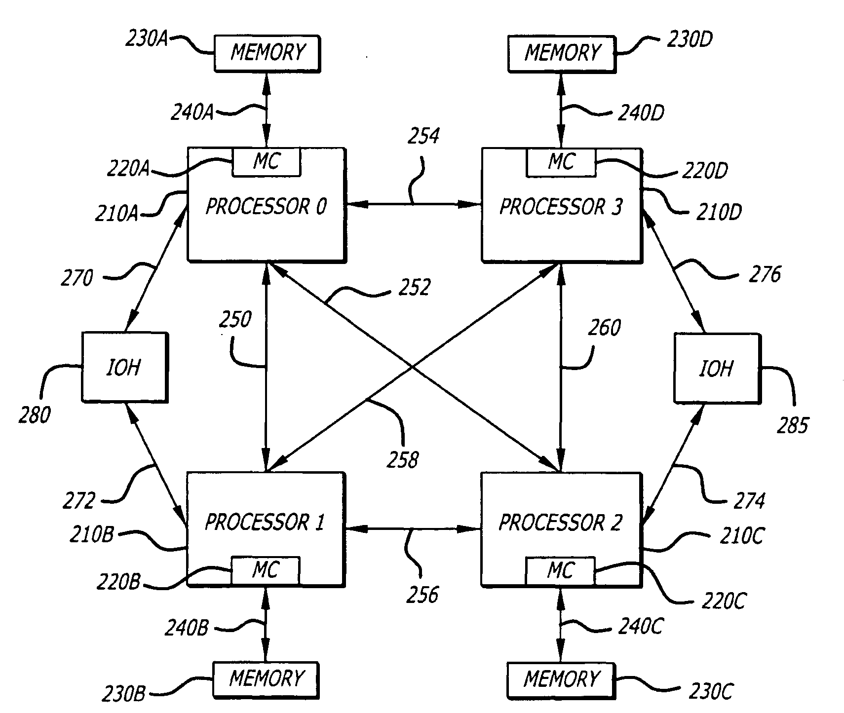
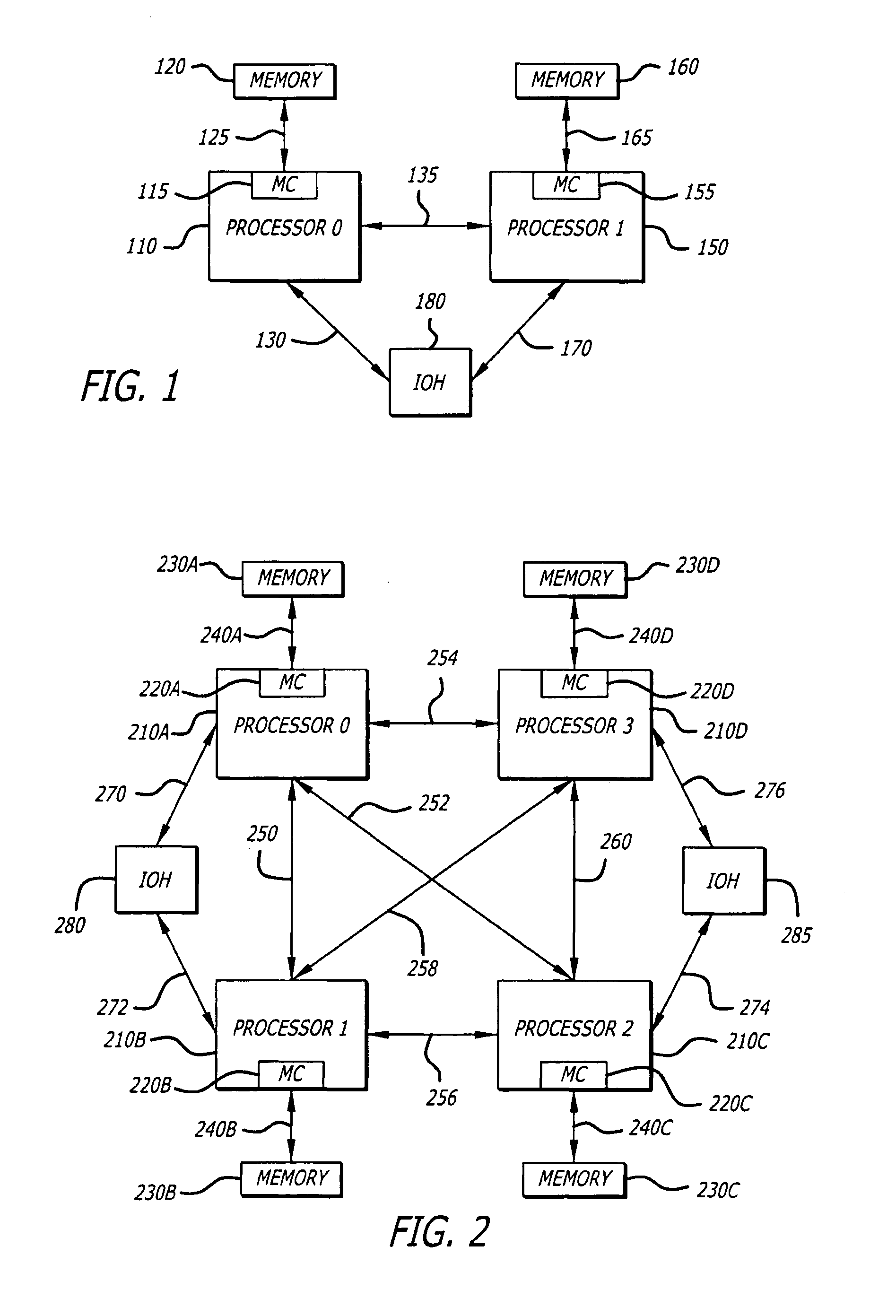
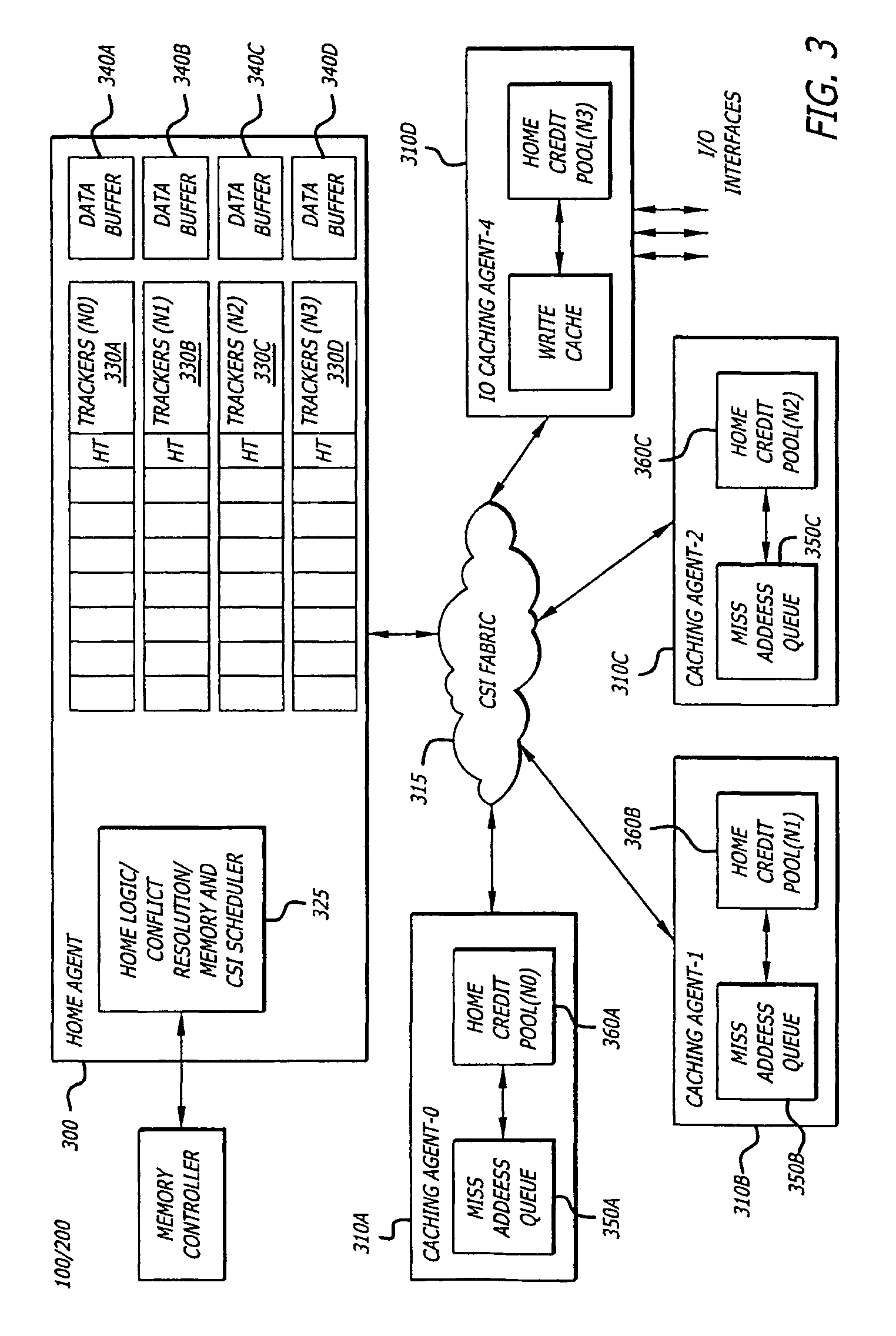
[0011]In the following description, certain terminology is used to describe features of the invention. For example, the term “device” or “agent” is general and may be used to describe any electrical component coupled to a link. A “link or interconnect” is generally defined as an information-carrying medium that establishes a communication pathway for messages, namely information placed in a predetermined format. The link or interconnect may be a wired physical medium (e.g., a bus, one or more electrical wires, trace, cable, etc.) or a wireless medium (e.g., air in combination with wireless signaling technology).

[0012]In one embodiment, the claimed subject matter allows using an aggressive idle timeout value to transition into low link power state while minimizing the latency to transactions that wake the links up from a low power state. In one aspect, the claimed subject matter optimizes power and performance tradeoff.

[0013]The term “home agent” is broadly defined as a device that p...


PUM


Abstract

A proposal for power management control of an interconnect structure based on power state transition control. The power state transition is based on generating early warning signals and an idle timeout value setting based on response time and detection of subsequent requests.

Description

FIELD[0001]Embodiments of the invention relate to the field of partitioning, and according to one embodiment, a method and apparatus, and system for power management of a link interconnect.GENERAL BACKGROUND[0002]Power management schemes allow for reducing power consumption for various types of systems and integrated devices, such as, servers, laptops, processors and desktops. With the introduction of processors with multiple cores, power management becomes a major concern because of the increase in cores operating at high frequencies and voltages and need to adhere to various power constraints, such as, thermal limits, maximum current, and Vcc range.[0003]A link interconnect allows communication between devices and functional blocks. Some examples of interconnects are shared buses and point to point links. The links may be in different power states depending on the traffic and each state allows different level of power and performance tradeoff. A link may be transitioned to a low p...

Claims


Application Information

Patent Timeline
IPC IPC(8): G06F1/00
CPCG06F1/3203G06F1/3253Y02B60/126Y02B60/1235G06F1/3278Y02D10/00G06F13/16
Inventor HALLNOR, ERIK G.FANG, ZHENROTITHOR, HEMANT G.
Owner INTEL CORP
Learn More