
Hardware description language and a system and methods for electronic design

a technology of electronic design and description language, applied in the field of electronic design hardware description language and a system and method, can solve the problems of time-consuming and error-prone repetition of such behavior descriptions, easy to be too large in module proliferation, and easy to write d-flip-flop instantiation about as tedious, so as to eliminate the possibility of repeating the behavior of a commonly used design obj

Inactive Publication Date: 2009-11-26
YAU DANIEL
View PDF1 Cites 3 Cited by
  • Summary
  • Abstract
  • Description
  • Claims
  • Application Information

AI Technical Summary

Benefits of technology

[0010]The object command does not necessarily contain the information of the object behavior so that the repetitive coding of the behavior of a commonly used design object can be eliminated.

Problems solved by technology

It is time-consuming and error-prone to repeat such behavior description in the design process.
However, the module instantiation has the following drawbacks: (1) the instantiation of a logic block with a modest complexity requires as much code as specifying the behavior of the logic block; (2) the instantiation requires that the connection of every connected port being explicitly specified, while many of such connections are not of the primary interest of the designers; (3) the need to use a large number of variations of a commonly-used logic block pushes the proliferation of the modules in the design library to be instantiated.
Writing an instantiation of a D-flip-flop is about as tedious as writing the behavior model of the D-flip-flop.
Even though the connections of these signals are essential for the correct behavior of the modules, the repetitive typing of these port names and the signal names, to which they are connected, is counter-productive and is not the primary focus of the design work.
The module proliferation can easily be too excessive if there is more than one variable of interest.
However, the parameterization has its limitations in such verification-centric standard HDL.

Method used


Image

  • Hardware description language and a system and methods for electronic design
  • Hardware description language and a system and methods for electronic design
  • Hardware description language and a system and methods for electronic design

Examples


Embodiment Construction

[0032]While this invention may be applied in the embodiments of various forms, it is shown in the drawings and will herein be described in specific embodiments. The detailed description in these specific embodiments is to be considered as examples of the invention and not to limit the invention in these embodiments as shown and described.

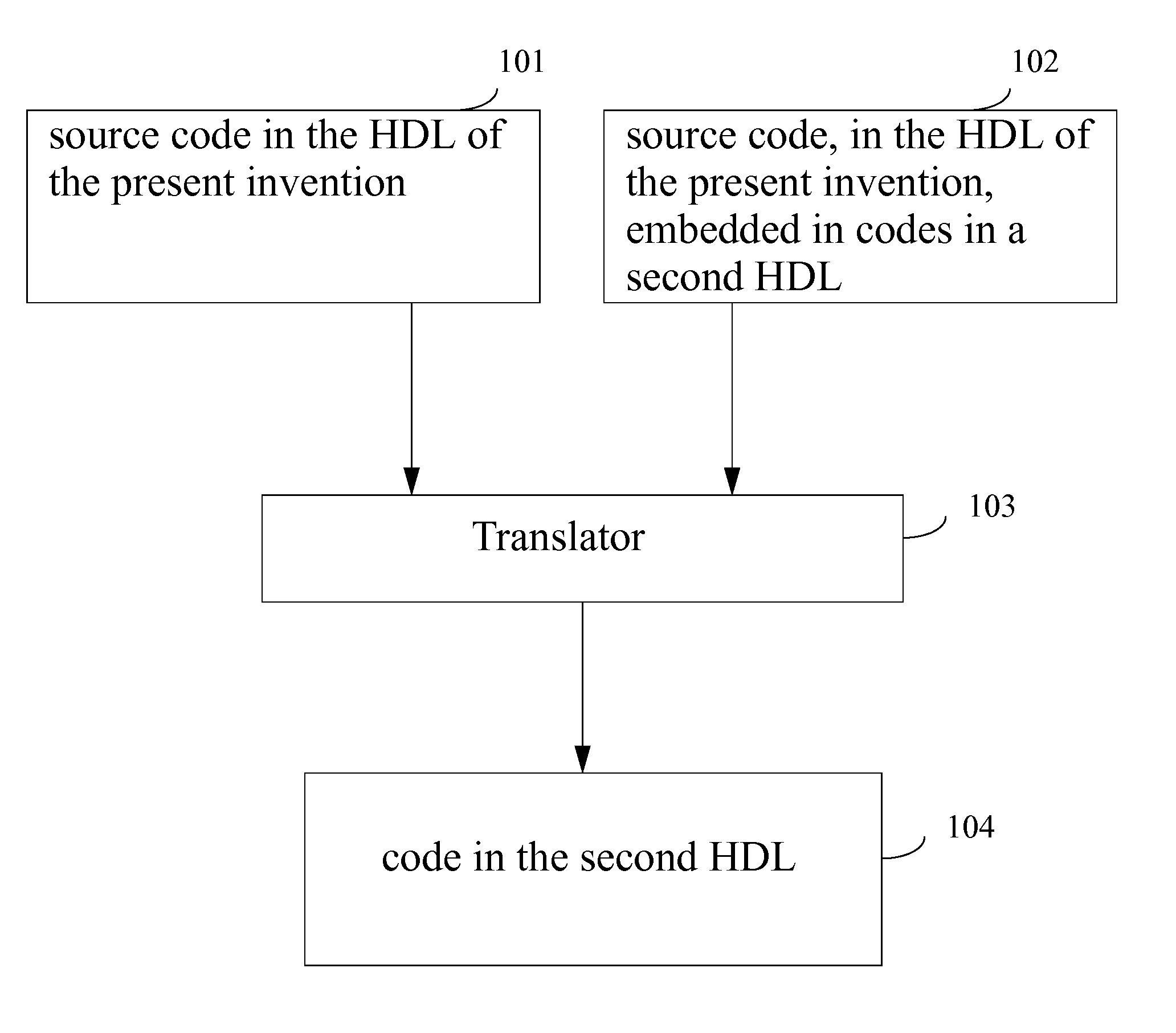
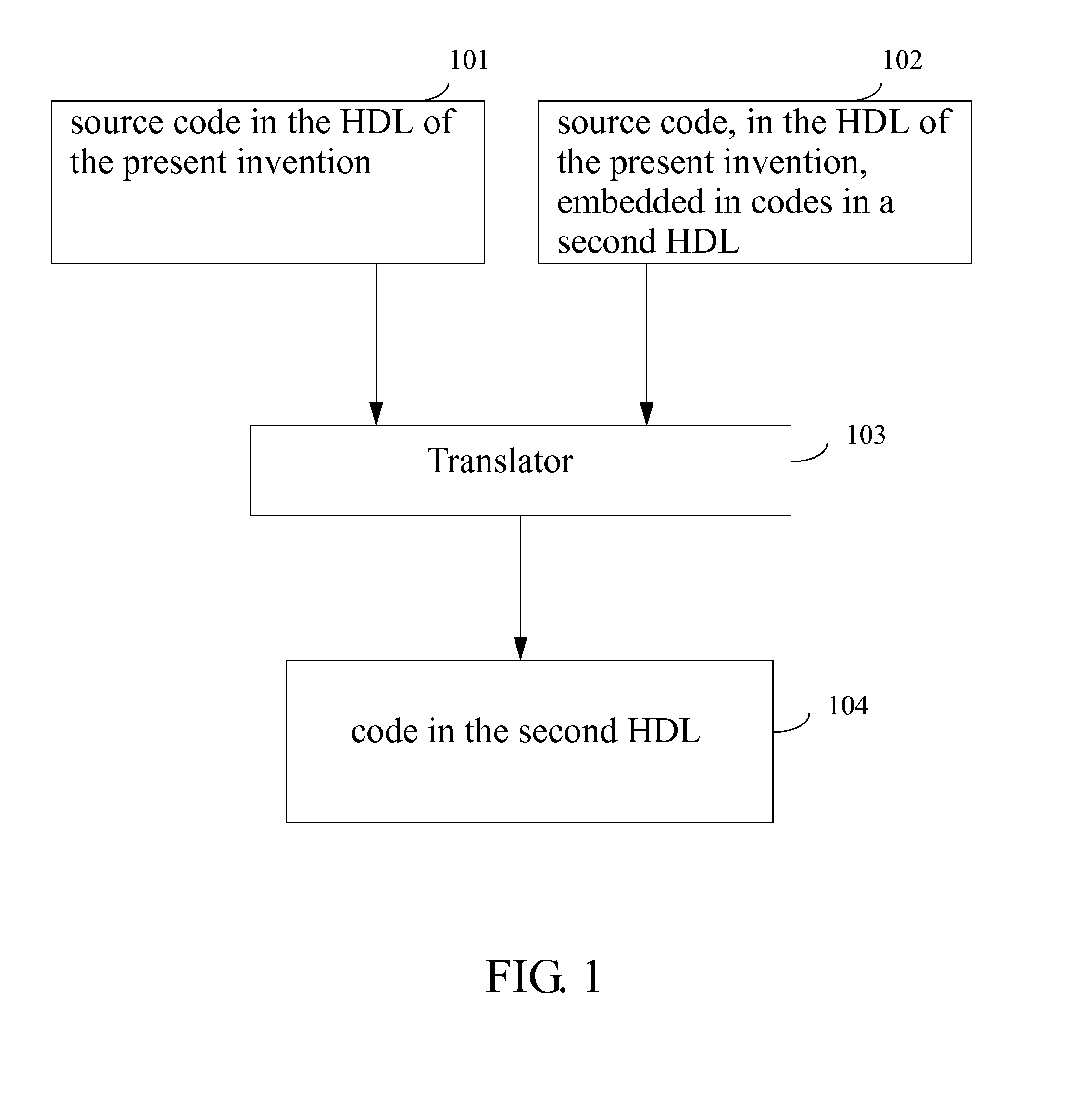
[0033]The present invention relates to a hardware description language that can be translated to a second hardware description language, such as Verilog-HDL or VHDL. The source codes may contain only the language constructs of the hardware description language, such as shown in 101 of FIG. 1, or it may contain the language constructs of the hardware description language embedded in the codes of a second hardware description language, as shown in 102 of FIG. 1. The source codes in 101, or the source codes in 102, can be read by a translator, shown in 103 of FIG. 1. The translator converts the source codes into codes in the second hardware description...


PUM


Abstract

A Hardware Description Language (HDL) comprising of a plurality of object commands, a plurality of compile commands and a plurality of comment styles is used in methods of electronic circuit design. An object command in the HDL defines a logic object, which can be as simple as a piece of wire or as complex as a priority-encoded arbitrator with a variable number of requesters. A Register Transfer Level (RTL) design in the HDL can be translated into a set of generic gates and instantiated library modules for design verification and synthesis. The design can also be translated to a target hardware description language such as Verilog-HDL or VHDL to feed into a conventional design flow.

Description

FIELD OF THE INVENTION[0001]The presented invention relates to defining a hardware description language to specify the design of an electronic design, and to methods to translate the hardware description language to a standard hardware description language, such as Verilog-HDL or VHDL.BACKGROUND OF THE INVENTION[0002]The standardized and well-accepted hardware description languages, Verilog-HDL and VHDL are defined primarily for verifying an electronic design. They emphasize the clarity of the behavior of the design coded in such languages. This emphasis requires the behavior details of a commonly used logic block being described every time such a logic block is written. It is time-consuming and error-prone to repeat such behavior description in the design process. A designer's primary interest to use a commonly used logic block is to connect them in the design, rather than to specify their behavior in the design. A designer wants to specify the behavior of a logic block only if the...

Claims


Application Information

Patent Timeline
IPC IPC(8): G06F17/50
CPCG06F17/5045G06F30/30
Inventor YAU, DANIEL
Owner YAU DANIEL
Learn More