Linear actuator

Inactive Publication Date: 2009-12-03
MOTECK ELECTRIC CORP
View PDF5 Cites 32 Cited by
  • Summary
  • Abstract
  • Description
  • Claims
  • Application Information

AI Technical Summary

Benefits of technology

[0012]The housing comprises a tubular front coupling portion formed of a front part of the first half shel

Problems solved by technology

In actual practice, this design of linear actuat

Method used


Image

  • Linear actuator
  • Linear actuator
  • Linear actuator

Examples


Embodiment Construction

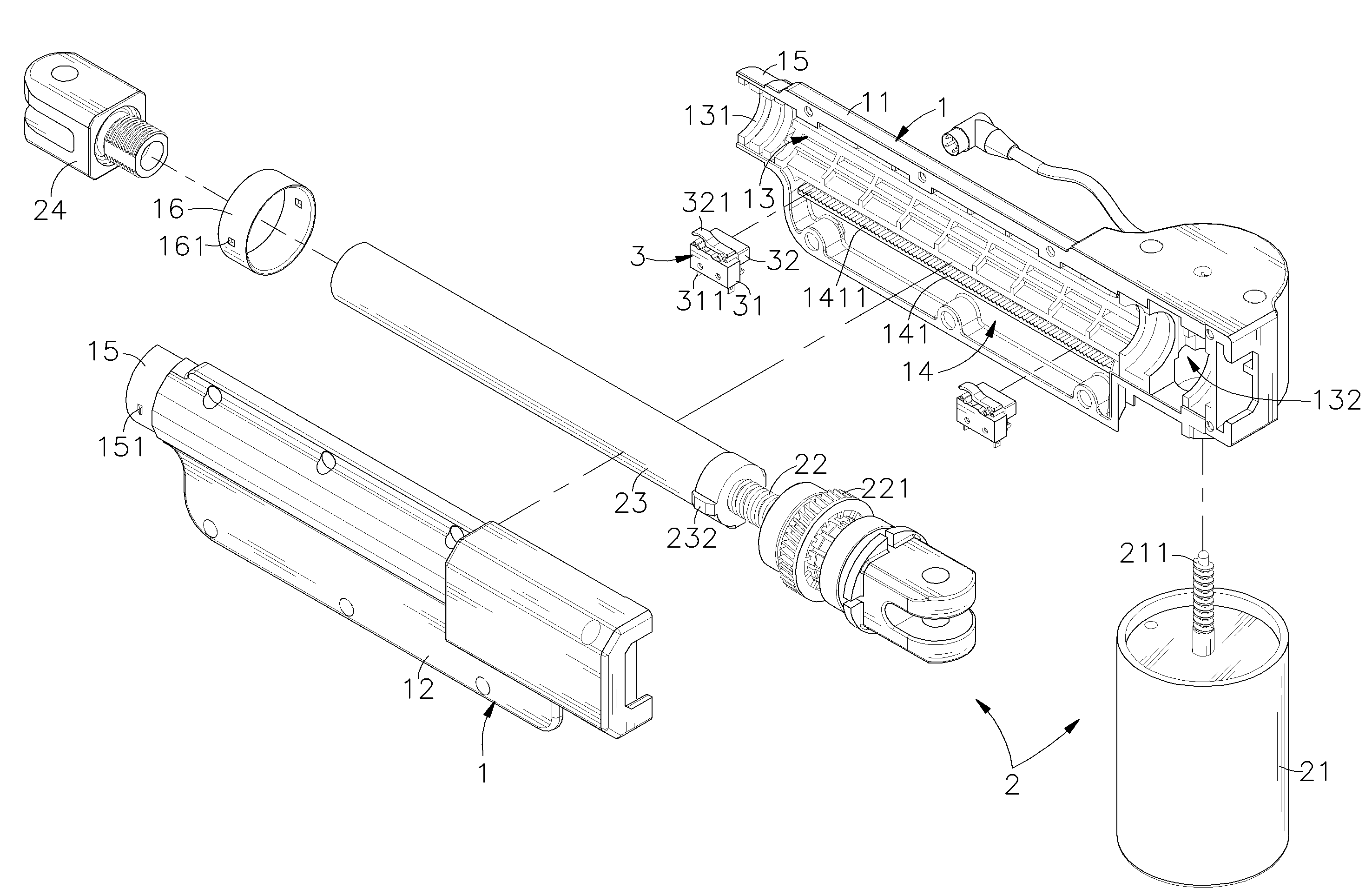
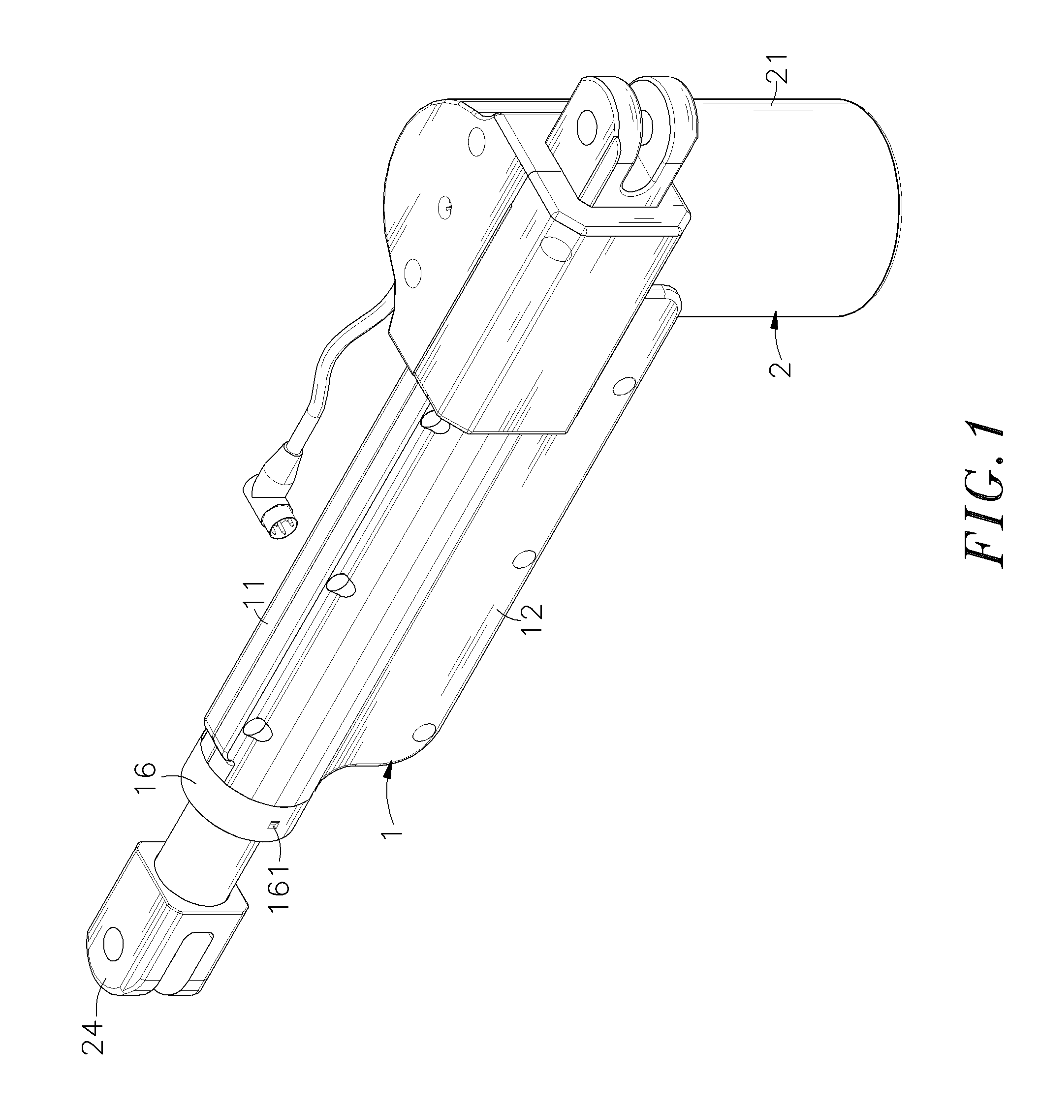
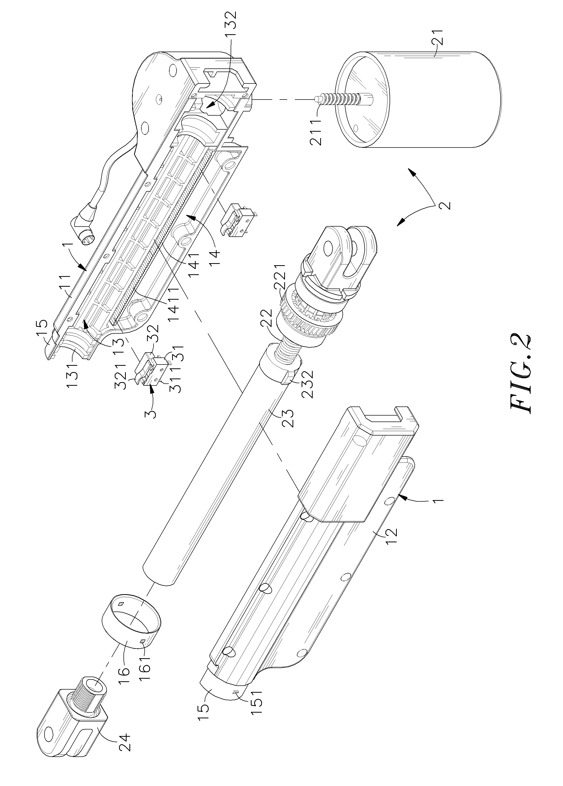
[0020]Referring to FIGS. 1˜4, a linear actuator in accordance with the present invention is shown comprising a housing 1, a driving mechanism 2 and at least one, for example, two limit switches 3.

[0021]The housing 1 is formed of a first half shell 11 and a second half shell 12, having an accommodation chamber 13 extending along the length thereof, a front opening 131 located on one end of the accommodation chamber 13, a rear compartment 132 located on the other end of the accommodation chamber 13, a bottom receiving chamber 14 located on the bottom side of the accommodation chamber 13, a longitudinal seat 141 set between the accommodation chamber 13 and the bottom receiving chamber 14, a series of transverse grooves 1411 located on the longitudinal seat 141 and facing the inside of the accommodation chamber 13, a tubular front coupling portion 15 extending around the front opening 131, at least one, for example, and two raised portions 151 protruded from the periphery at two opposit...


PUM


Abstract

A linear actuator includes a housing formed of a first half shell and a second half shell and defining an accommodation chamber, a front opening in front of the accommodation chamber and a receiving chamber at the bottom side of the accommodation chamber, a driving mechanism having a push rod movably mounted in the accommodation chamber and extending out of the front opening, a motor mounted outside the accommodation chamber and a spindle coupled to and rotatable by the motor for causing the transmission shaft to reciprocate, and limit switches detachably mounted in the receiving chamber for stopping the motor upon movement of the transmission shaft to a front or rear limit position.

Description

[0001]This application claims the priority benefit of Taiwan patent application number 097209674 filed on Jun. 2, 2008.BACKGROUND OF THE INVENTION[0002]1. Field of the Invention[0003]The present invention relates to a linear actuator and more particularly, to the structural design of the housing of a linear actuator, which is formed of two half shells, facilitating installation and position adjustment of limit switches.[0004]2. Description of the Related Art[0005]Many linear actuators are known and intensively used in electric hospital beds, treadmills and to facilitate position adjustment. During application of a linear actuator, limit switches are usually used and respectively mounted in the start end and finish end to control the forward and return strokes of the linear actuator. When a push block of a nut of the linear actuator touches the limit switch at the finish end during the forward stroke, the limit switch is triggered to stop forward movement of the linear actuator. On t...

Claims


Application Information

Patent Timeline
IPC IPC(8): F16H25/20
CPCF16H25/2015F16H2025/2031Y10T74/18688F16H2025/209F16H2025/2084
Inventor TSENG, HSIEN-TELIU, CHUN-CHIH
Owner MOTECK ELECTRIC CORP
Why Eureka
Try Eureka