Apparatus for defeating high energy projectiles

a technology of high-energy projectiles and armor, applied in the field of armor systems, can solve the problems of heavy armor thickness, high cost, and obvious detrimental effects of occurrence on the system and personnel of the vehicle, and achieve the effects of reducing the number of vehicles using conventional armor

Inactive Publication Date: 2009-12-03
FORCE PROTECTION TECH
View PDF103 Cites 26 Cited by
  • Summary
  • Abstract
  • Description
  • Claims
  • Application Information

AI Technical Summary

Benefits of technology

[0014]The present invention seeks to utilize the heretofore unappreciated ability of some low density, non-metal composite materials to degrade the effectiveness of such high energy project...

Problems solved by technology

Such an occurrence can, obviously, have very significant detrimental effects on the systems and personnel within a vehicle having its armor defeated in such a manner.
For that reason, and the fact such weapons are effective, has proved troublesome to vehicles using conventional armor.
While...

Method used


Image

  • Apparatus for defeating high energy projectiles
  • Apparatus for defeating high energy projectiles
  • Apparatus for defeating high energy projectiles

Examples


first embodiment

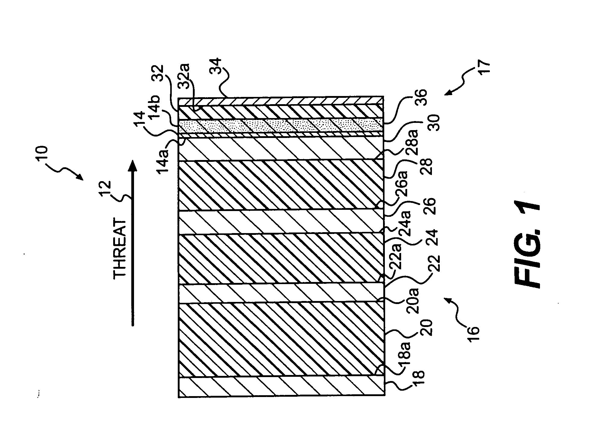
[0030]FIG. 1 presents the invention, namely an armor system generally designated by the numeral 10 for protecting a vehicle from high energy projectiles. In the following discussion, the projectile has an expected trajectory relative to the vehicle, which trajectory is designated by the numeral 12 in the figures. Trajectory 12 establishes a direction for understanding certain terms used in the following discussion, such as “leading,”“rear” or “behind,”“front,” etc., namely the direction that the components of armor system 10 would successively confront the projectile as it approached the vehicle hull, designated generally by the numeral 14. Moreover, the terms are “exterior” and “interior” as used in conjunction with the vehicle hull 14 are given their usual meanings.

[0031]Specifically, armor system 10 in the FIG. 1 embodiment includes exterior armor subsystem 16 and interior armor subsystem 17. Exterior armor subsystem 16 more particularly includes a leading sheet-like layer 18 of ...

embodiment 10

[0036]An example of a particular armor system constructed in accordance with embodiment 10 depicted in FIG. 1 may have each of leading aluminum layer 18 and the first “intermediate” (i.e., positioned between the leading layer and the hull) aluminum layer 22 to be about 1¼ inch thick sheets, while each of the second and third intermediate aluminum layers 26 and 30 be about 1½ inch sheets. The first intermediate low density polypropylene composite layer 20 may be about 4½ inches thick, and the second and third intermediate low density polypropylene layers 24 and 28 be about 1½ inches thick. Also, foam layer / space 36 of interior armor subsystem 17 may be about ¾ inch thick; low density polypropylene composite layer 32 about ¾ inch thick; and Kevlar® / E-Glass hybrid layer 34 about ½ inch thick.

[0037]It is contemplated that the exterior armor subsystem 16 as depicted in the embodiment of FIG. 1 can be used without the particular interior armor subsystem 17 shown, or any interior armor mat...

second embodiment

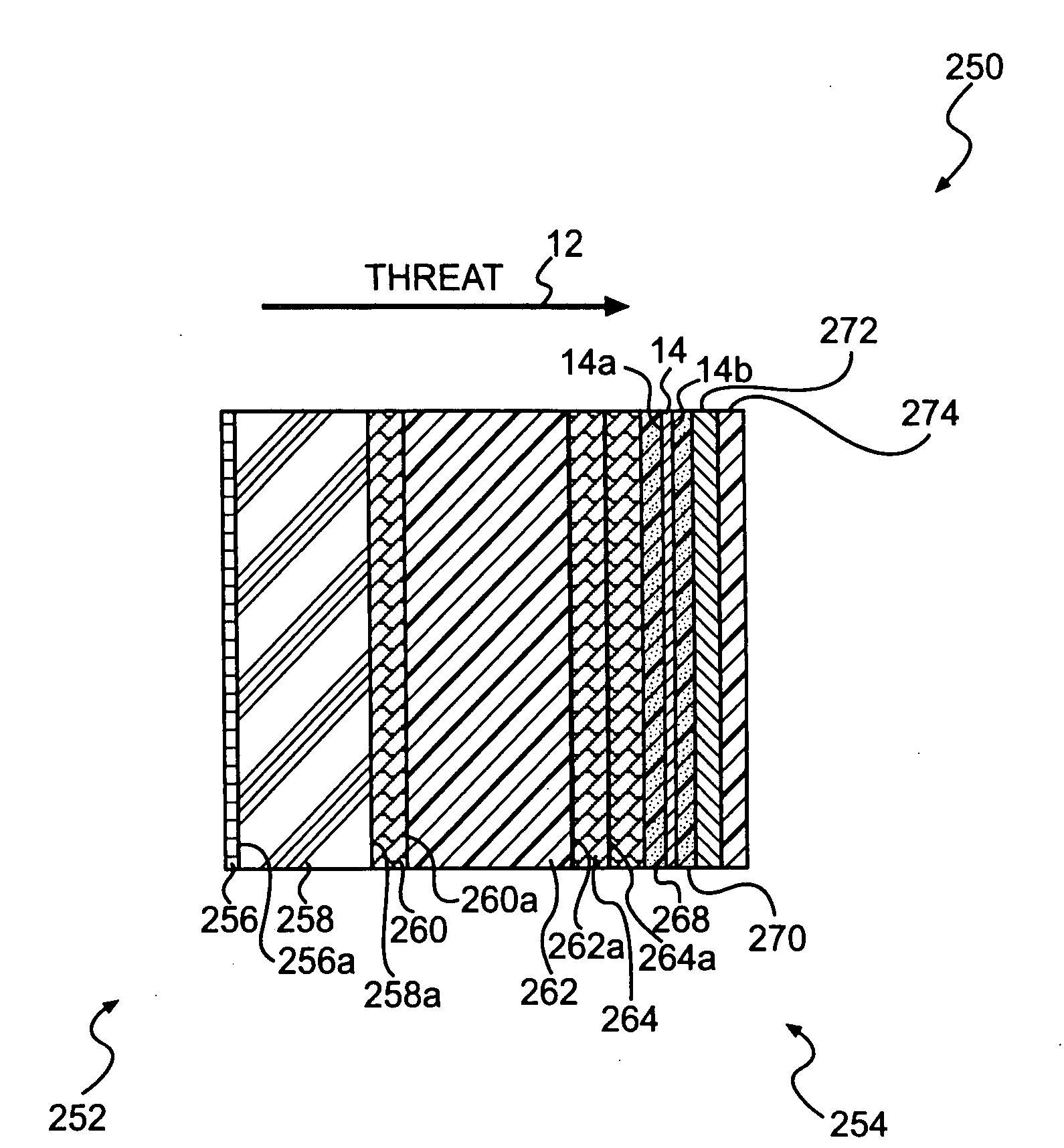
[0039]FIG. 2 depicts the armor system of the present invention, namely armor subsystem 40, which includes exterior subsystem 42 and which also may include an interior armor system 44. Interior armor system 44 in the FIG. 2 embodiment is substantially the same as interior armor subsystem 17 depicted in FIG. 1 embodiment and will therefore not be discussed further.

[0040]As in the exterior armor subsystem 16 in the FIG. 1 embodiment, the exterior subsystem 42 in the embodiment shown in FIG. 2 includes a leading layer 46 of high strength aluminum followed by alternating layers of a low density polypropylene composite and a high strength aluminum. In particular, exterior subsystem 42 includes leading high strength aluminum layer 46; a first intermediate layer 48 of low density polypropylene composite abutting rear surface 46a of leading aluminum layer 46; a first intermediate layer 50 of a high strength aluminum abutting rear surface 48a of low density polypropylene composite layer 48; s...


PUM

PropertyMeasurementUnit
Densityaaaaaaaaaa
Strengthaaaaaaaaaa
Distanceaaaaaaaaaa

Abstract

The disclosed armor system for protecting a vehicle from high energy projectiles includes a leading layer, relative to the projectile trajectory, positioned exterior to the hull; a first plurality of sheet-like layers of a low density material positioned between the leading layer and the hull; and a second plurality of sheet-like high strength metal layers positioned between the leading layer and the hull. The individual ones of the first plurality of high strength metal layers are positioned alternating with, and to the rear of, individual ones of the second plurality of low density material layers. The leading layer can be one of a sheet-like metal layer, a metalicized grid layer, and the outer-most layer of the first plurality of low density materials layers. The materials of the high strength metal layers may be selected from high strength steel and high strength aluminum, and the materials of the low density material may be selected from low density polypropylene composites and R-Glass composites.

Description

PRIORITY[0001]This non-provisional application claims priority to U.S. Provisional Patent Application No. 61 / 071,917 filed May 27, 2008.FIELD OF THE INVENTION[0002]The present invention relates to an armor system that resists penetration by high energy solid projectiles and high velocity jets e.g. from hollow charge weapons such as rocket propelled grenades.BACKGROUND OF THE INVENTION[0003]Conventional armor is subjected to a variety of projectiles designed to defeat the armor by either penetrating the armor with a solid or jet-like object or by inducing shock waves in the armor that are reflected in a manner to cause spalling of the armor such that an opening is formed and the penetrator (usually stuck to a portion of the armor) passes through the armor, or an inner layer of the armor spalls and is projected at high velocity without physical penetration of the armor.[0004]Some anti-armor weapons are propelled to the outer surface of the armor where a shaped charge is exploded to fo...

Claims


Application Information

Patent Timeline
IPC IPC(8): F41H5/04
CPCF41H5/04F41H5/0457F41H5/0442
Inventor JOYNT, VERNON P.COLE, ROBERT A.BORDERS, THOMAS E.
Owner FORCE PROTECTION TECH
Why Eureka
Try Eureka