Eureka AIR delivers breakthrough ideas for toughest innovation challenges, trusted by R&D personnel around the world.

Gear assemblies

a gear assembly and gear technology, applied in the direction of gear details, mechanical equipment, transportation and packaging, etc., can solve the problem of unwanted rattle noise in the axial clearance of the second bearing, and achieve the effect of convenient access for maintenan

Active Publication Date: 2009-12-03
TRW LIMITED
View PDF11 Cites 10 Cited by
  • Summary
  • Abstract
  • Description
  • Claims
  • Application Information

AI Technical Summary

Benefits of technology

[0010]In order to permit the first bearing means to move relative to the housing when subjected to such a tilting load, the second bearing means may be adapted to permit a degree of tilt of the input shaft within the bearing relative to the housing. This tilting bearing is preferably the one closest to the motor to minimise misalignment between motor rotor and input shaft for a given amount of tilt. The bearing may allow an angle of tilt of up + / −0.1 degrees or higher, say up to + / −0.2 degrees or thereabouts.
[0028]The bearing means may additionally include a further bearing assembly comprising a fixed race secured to the gearbox housing and a moving race that is free to move relative to the fixed housing by rolling elements such as balls located between the fixed and moving races to define a thrust bearing, the moving race providing a reaction face for the biasing means, and in which the moving race can move in a direction radial to the axis of the input shaft whilst preventing translation of the moving race orthogonal to the plane of articulation.
[0033]The locating bar for the spring may be supported at its ends within half round locating grooves provided in the support frame. A cover may be provided which seals the support frame to the support collar when assembled whilst permitting access to the adjustable fastening. The inside of the cover may be provided with further half round grooves which surround the locating bar to prevent it from slipping out of position. The cover may be a snap fit to the frame.
[0035]As will be appreciated, it is envisaged that the biasing means may be provided as an integral part of the first bearing assembly. This has the advantage that it can be installed or removed in one process as part of the installation of the first bearing assembly. It is also easy to access for maintenance by being located at the free end of the input shaft.

Problems solved by technology

The axial clearance in the second bearing is a source of unwanted rattle noise.

Method used


Image

  • Gear assemblies
  • Gear assemblies
  • Gear assemblies

Examples


Embodiment Construction

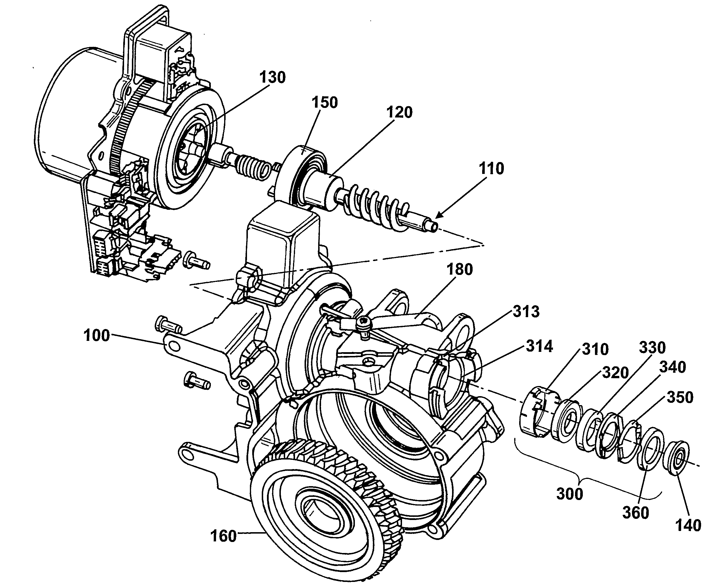
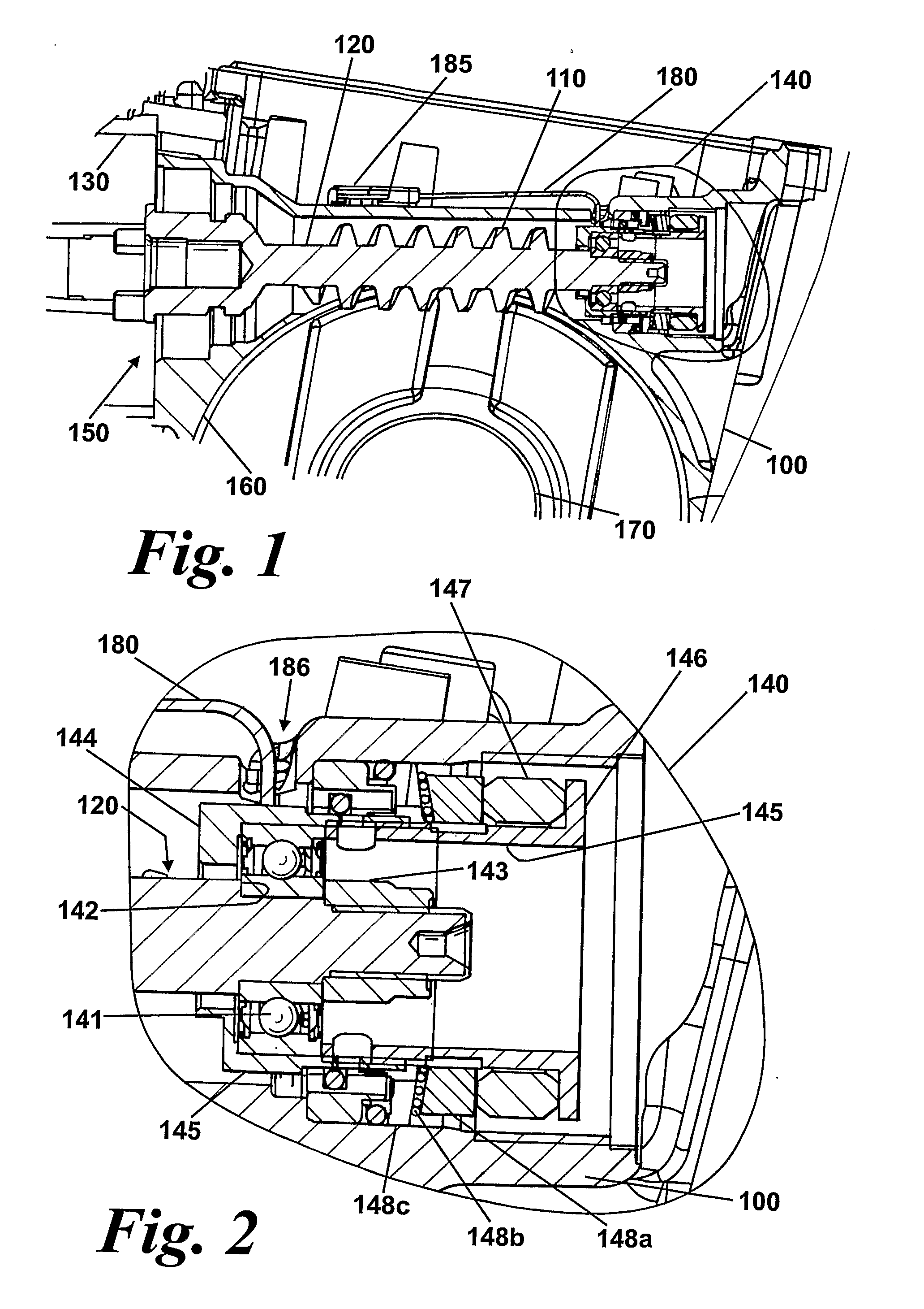
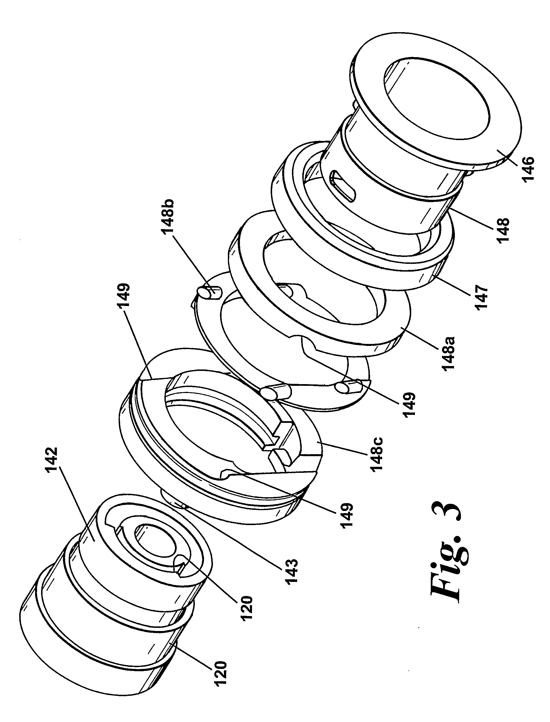
[0051]A first embodiment of a gearbox assembly is shown in FIG. 1. It comprises a cast metal housing 100. The housing provides a mating face for a motor which is coupled to a worm gear 110 provided on an input shaft 120 inside the housing. The rotor 130 of the motor can be seen to the left of the Figure. The motor and the housing are secured together by bolts or other fastenings (not shown). The input shaft 120 is supported by two bearing assemblies 140, 150—one towards each end, that are located within recesses in the gearbox housing 100.

[0052]A wheel gear 160 is also provided on an output shaft 170 which is also supported by bearings (not shown) on either side of the wheel. Again these bearings are supported in recesses (not shown) in the housing. This output shaft is typically part of a steering shaft which operatively couples a steering wheel to one or more road wheels of a vehicle. The shaft in the Figure extends out of the paper towards the reader.

[0053]The teeth of the wheel ...


PUM


Abstract

In a gearbox for use in an electric power assisted steering system comprises a housing, an input shaft located at least partially within the housing which carries a worm gear and includes means for coupling to a motor rotor at one end, an output shaft located at least partially within the housing which carries a wheel gear, and a first bearing means which supports the input shaft at a side of the worm distal from the end of the shaft which connects to the motor rotor and second bearing means which supports the input shaft at the other side of the worm, the invention comprises further providing a first biasing means adapted to apply an axial load to the input shaft to bias the axial clearance in the second bearing, the second biasing means acting upon a part of the first bearing means; and a second biasing means adapted to apply a radial load to the input shaft to bias the worm into engagement with the wheel gear, the second biasing means also acting upon a part of the first bearing means.

Description

CROSS-REFERENCE TO RELATED APPLICATIONS[0001]This application is a National Stage of International Application No. PCT / GB2007 / 001581 filed May 1, 2007, the disclosures of which are incorporated herein by reference in entirety, and which claimed priority to Great Britain Patent Application No. 0700052.4 filed Jan. 3, 2007 and Great Britain Patent Application No. 0608577.3 filed May 2, 2006, the disclosures of which are incorporated herein by reference in entirety.BACKGROUND OF THE INVENTION[0002]This invention relates to improvements in gear assemblies and in particular to gear assemblies for use in electric power assisted steering systems of the kind which incorporate a worm and wheel gear assembly for transferring torque from an electric motor to a steering shaft or output shaft operatively connected thereto.[0003]It is known to provide a power steering system for a vehicle comprising an electric motor having a stator and a rotor, an input shaft operatively connected to the rotor a...

Claims


Application Information

Patent Timeline
Patent Type & Authority Applications(United States)
IPC IPC(8): B62D5/04
CPCB62D5/0409F16H2057/0213F16H57/021F16H55/24
Inventor WILKES, MARK ANTHONY
Owner TRW LIMITED
Why Eureka
Eureka Blog
Learn More