Lateral position detection for friction stir systems

a technology of friction stir and lateral position detection, which is applied in the direction of soldering apparatus, manufacturing tools,auxillary welding devices, etc., can solve the problems of loss of quality, substantial and complex material flow, and loss of weld quality of fsw

Inactive Publication Date: 2009-12-03
VANDERBILT UNIV
View PDF10 Cites 39 Cited by
  • Summary
  • Abstract
  • Description
  • Claims
  • Application Information

AI Technical Summary

Problems solved by technology

Analogous to FSW, in FSP there is generally substantial and complex material flow.
As known in the art, welds from FSW can experience a loss in weld quality when the system parameters and conditions are not well set.
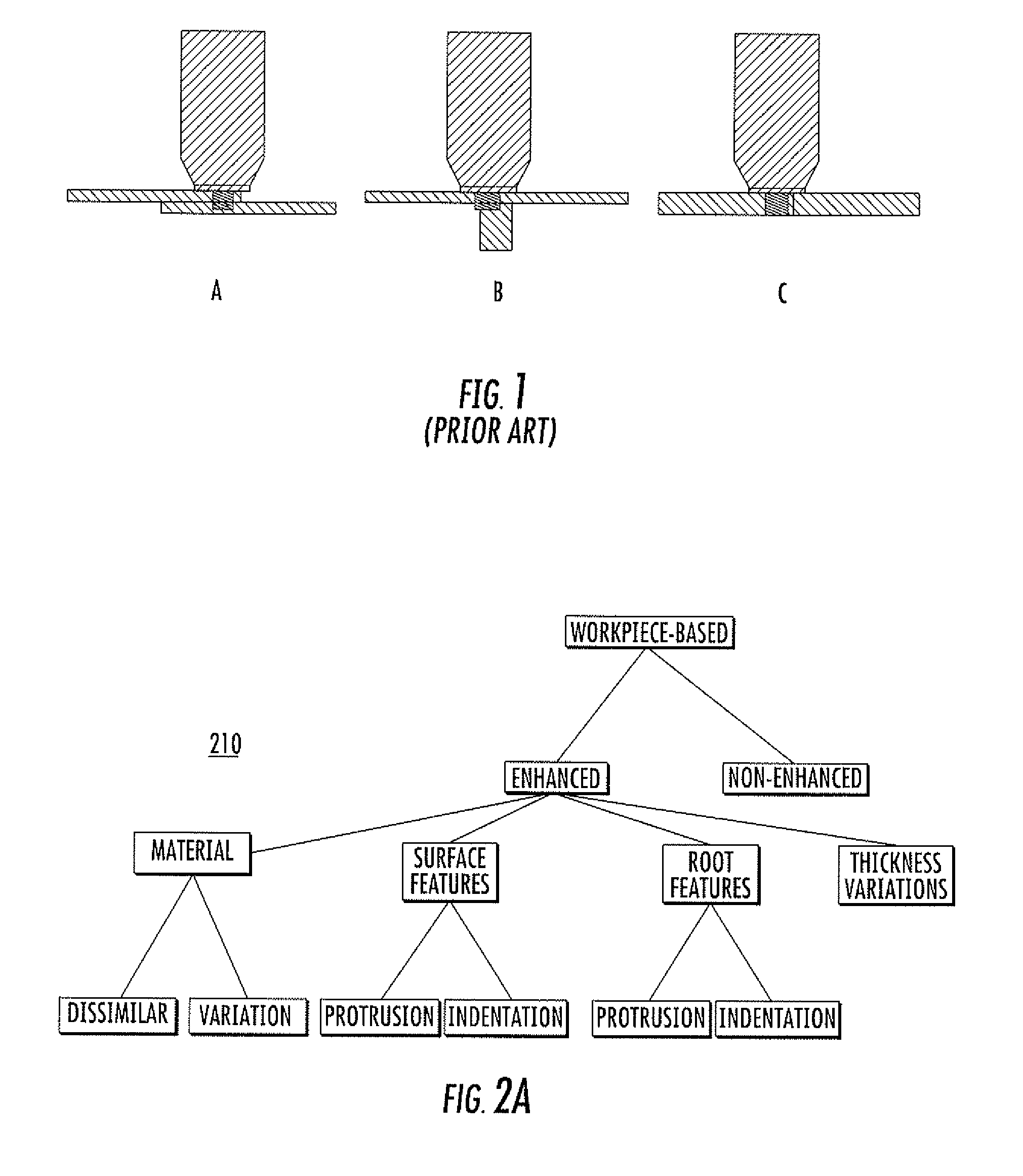
For instance, in the case of FSW, loss of quality can occur if the welding tool rotates too slowly, or too quickly, or if the probe is not the correct length for the material (e.g. a probe in butt-welding extends only halfway through the material, leaving the lower half of the seam un-bonded).
In FSW, lateral misalignment can cause poor quality welds.
In FSP, lateral misalignment can cause unintended microstructural results.
In lap-welding, lateral misalignment can arise when the probe is located entirely within the material but the shoulder of the tool is not completely in contact with the upper material.
This condition can result in a number of generally undesirable consequences that result from insufficient heat input due to less shoulder contact and thus less friction.
These changing conditions will cause changes in weld quality.
Lateral offset is known to cause deterioration of quality for T-joints in both the extended un-bonded region to the right of the probe as well as the loss of the material which is generally ejected to the left of the probe.
The resulting weld quality for significant lateral offset in butt-joints will likely be quite low.
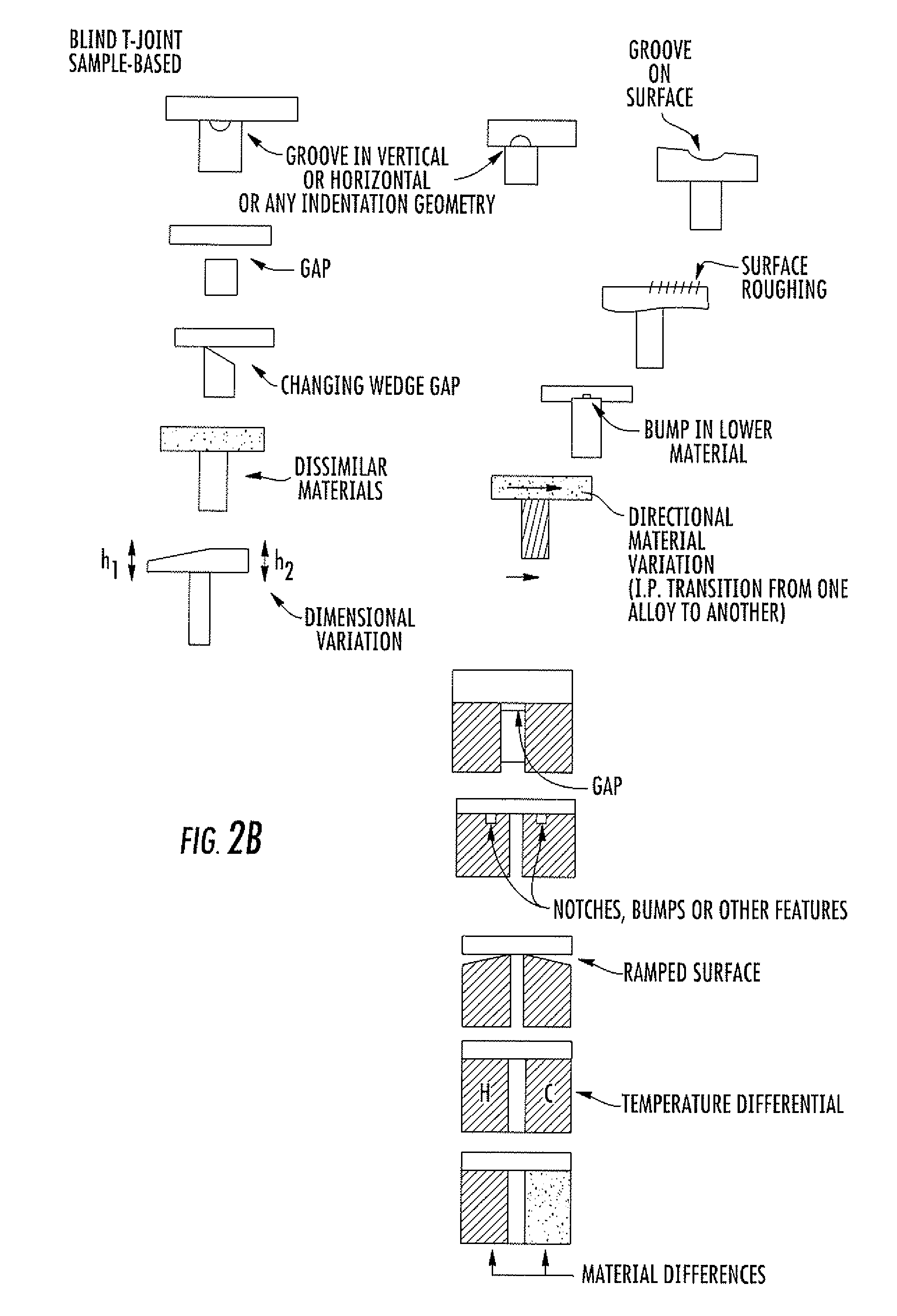
However, in other lap welds including blind T-joint, visualization is not generally possible.
In blind T-joints this inability results because the lower vertical member cannot be seen through the upper horizontal member.
Similarly, in certain FSP processes, visualization is not generally possible.
However, in certain configurations, information regarding the side of the center location may prove difficult to determine.
Such a misalignment could have serious effects on the weld quality.

Method used


Image

  • Lateral position detection for friction stir systems
  • Lateral position detection for friction stir systems
  • Lateral position detection for friction stir systems

Examples


Embodiment Construction

[0025]The present invention is described with reference to the attached figures, wherein like reference numerals are used throughout the figures to designate similar or equivalent elements. The figures are not drawn to scale and they are provided merely to illustrate the instant invention. Several aspects of the invention are described below with reference to example applications for illustration. It should be understood that numerous specific details, relationships, and methods are set forth to provide a full understanding of the invention. One having ordinary skill in the relevant art, however, will readily recognize that the invention can be practiced without one or more of the specific details or with other methods. In other instances, well-known structures or operations are not shown in detail to avoid obscuring the invention. The present invention is not limited by the illustrated ordering of acts or events, as some acts may occur in different orders and / or concurrently with o...


PUM

PropertyMeasurementUnit
axial forceaaaaaaaaaa
forcesaaaaaaaaaa
forceaaaaaaaaaa

Abstract

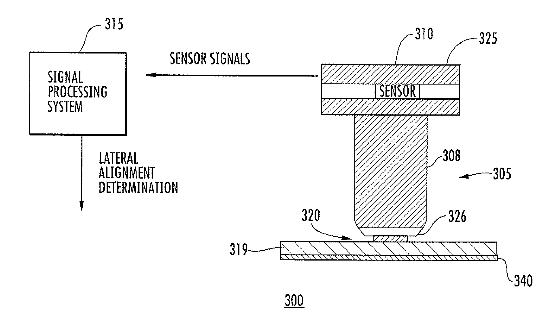
A friction stir system for processing at least a first workpiece includes a spindle actuator coupled to a rotary tool comprising a rotating member for contacting and processing the first workpiece. A detection system is provided for obtaining information related to a lateral alignment of the rotating member. The detection system comprises at least one sensor for measuring a force experienced by the rotary tool or a parameter related to the force experienced by the rotary tool during processing, wherein the sensor provides sensor signals. A signal processing system is coupled to receive and analyze the sensor signals and determine a lateral alignment of the rotating member relative to a selected lateral position, a selected path, or a direction to decrease a lateral distance relative to the selected lateral position or selected path. In one embodiment, the friction stir system can be embodied as a closed loop tracking system, such as a robot-based tracked friction stir welding (FSW) or friction stir processing (FSP) system.

Description

GOVERNMENT RIGHTS[0001]The United States Government has certain rights in embodiments of the present invention pursuant to prime contract No. W-7405-ENG-36 with the United States Department of Energy.FIELD OF THE INVENTION[0002]The present invention relates to friction stir systems (FSS) including friction stir welding (FSW) and friction stir processing (FSP) systems, and related position detection methodologies for such systems.BACKGROUND[0003]One FSS embodiment is FSW. FSW is a joining process where welding is accomplished via mechanical stirring at a temperature that is below the melting point of the material being welded. In FSW, the welding tool comprises a shoulder and a pin (also called a probe). The tool is rotated while traversing the weld line. The shoulder applies pressure and friction induced heat to the surface of the material while the probe plunges into the material and induces material flow.[0004]Another FSS embodiment is referred to as friction stir processing (FSP)...

Claims


Application Information

Patent Timeline
Patent Type & Authority Applications(United States)
IPC IPC(8): B23K31/12B23K20/12
CPCB23K20/125B23K2203/18B23K2203/10B23K2103/10B23K2103/18B23K2103/20
Inventor FLEMING, PAULLAMMLEIN, DAVIDCOOK, GEORGE E.WILKES, D. M.STRAUSS, ALVIN M.DELAPP, DAVIDHARTMAN, DANIEL A.
Owner VANDERBILT UNIV
Why Eureka
Try Eureka