Assembly and method for restricting spinning in a gyratory crusher

a gyratory crusher and spinning head technology, applied in the field of restricting spinning in a gyratory crusher, can solve the problems of complex overall solution, increased tendency of crushing head to spin, and increased tendency of crushing head to spin, and achieve the effect of fewer mechanical components

Inactive Publication Date: 2009-12-03
SANDVIK INTELLECTUAL PROPERTY AB
View PDF0 Cites 37 Cited by
  • Summary
  • Abstract
  • Description
  • Claims
  • Application Information

AI Technical Summary

Benefits of technology

[0019]The disclosed method and crusher system enables spinning restriction to be achieved with fewer mechanical components and / or in a more reliable manner. Further advantages and features will be apparent from the following description and the appended claims.

Problems solved by technology

The tendency of an anti-reverse to break down leads to complex overall solutions, including different mechanisms to protect the anti-reverse as well as undesirable stoppages.
If no material to be crushed is present in the gap, it is likely that the crushing head will have an increased tendency to spin.
If no material or only little material to be crushed is about to be fed, it is likely that before long the crushing head will show an increased tendency to spin.
If the crushing head rotates faster than its normal rotational speed when rollingly engaged, it is likely that the crushing head will have an increased tendency to spin.
If the crushing head rotates in a direction opposite to the direction of the rotation that would be caused by a rolling engagement between the crushing head and said second crushing shell, it is likely that the crushing head will have an increased tendency to spin.
As a result the crushing head has an increased tendency to spin.

Method used


Image

  • Assembly and method for restricting spinning in a gyratory crusher
  • Assembly and method for restricting spinning in a gyratory crusher
  • Assembly and method for restricting spinning in a gyratory crusher

Examples


Embodiment Construction

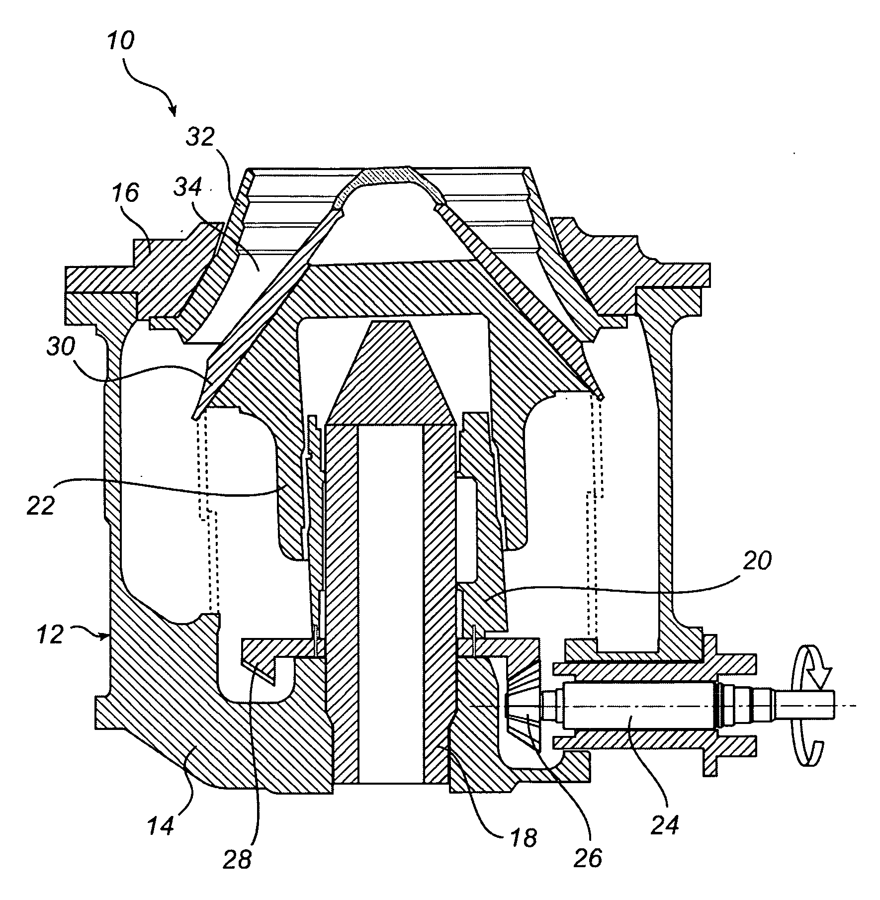
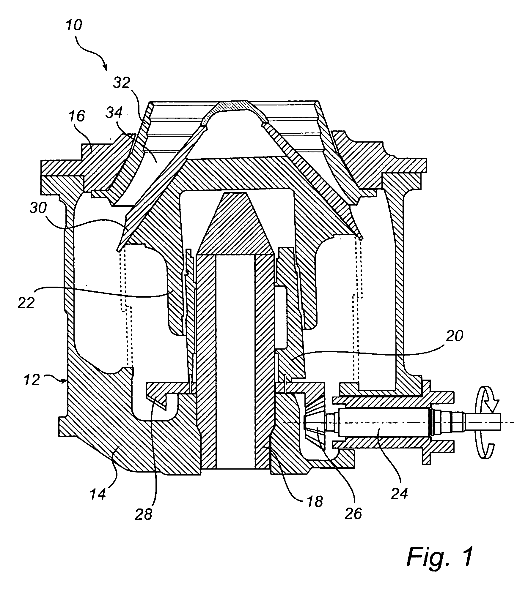
[0026]FIG. 1 illustrates schematically a gyratory crusher 10, which has a frame 12 comprising a frame bottom part 14 and a frame top part 16. A vertical shaft 18 is fixedly attached to the frame bottom part 14 of the frame 12. An eccentric 20 is rotatably arranged about the vertical shaft 18. A crushing head 22 is rotatably arranged about the eccentric 20, and thus about the vertical shaft 18. A drive shaft 24 is arranged to cause, by means of a conical gear wheel 26 in mesh with a gear rim 28 coupled to the eccentric 20, the eccentric 20 to rotate about the vertical shaft 18. The outer periphery of the eccentric 20 is slightly inclined relative to the vertical plane, as is illustrated in FIG. 1 and previously known, as such, in the art. The inclination of the outer periphery of the eccentric 20 means that also the crushing head 22 will be slightly inclined relative to the vertical plane.

[0027]A first crushing shell 30 is fixedly mounted on the crushing head 22. A second crushing sh...


PUM


Abstract

A crusher system includes a gyratory crusher, which has a crushing head, on which a first crushing shell is mounted; a frame, on which a second crushing shell is mounted; and a driving device, which is arranged to cause, by means of a rotating eccentric, the crushing head to execute a gyratory movement for crushing material. The crusher system includes a device for generating a signal that indicates the current tendency of the crushing head to spin; a device arranged to establish, based on the signal, a maximum allowable rotational speed for the eccentric; and a device arranged to adapt the rotational speed of the eccentric to a rotational speed that is lower than the maximum allowable rotational speed.

Description

CROSS-REFERENCE TO RELATED APPLICATIONS[0001]This application claims priority under 35 U.S.C. §119 to Swedish patent application No. 0801275-9 filed May 30, 2008; the entire contents of which are hereby incorporated by reference.TECHNICAL FIELD[0002]The present disclosure relates to restricting spinning in a gyratory crusher, which comprises a crushing head, on which a first crushing shell is mounted; a frame, on which a second crushing shell is mounted, which second crushing shell defines together with the first crushing shell a crushing gap; and a driving device arranged to cause, by means of a rotating eccentric, the crushing head to execute a gyratory movement with a view to crushing material that is introduced in the crushing gap.[0003]The present disclosure also concerns a crusher system comprising a gyratory crusher of the type stated above.BACKGROUND ART[0004]A gyratory crusher of the kind stated above can be used for crushing, for example, ore and stone material into smalle...

Claims


Application Information

Patent Timeline
Patent Type & Authority Applications(United States)
IPC IPC(8): B02C25/00B02C2/00
CPCB02C2/047B02C25/00B02C2/007
Inventor ERIKSSON, BENGT-ARNEGUNNARSSON, JOHAN
Owner SANDVIK INTELLECTUAL PROPERTY AB
Why Eureka
Try Eureka