Pressure vessel having improved sealing arrangement

Active Publication Date: 2011-05-12
YACHIYO IND CO LTD
View PDF6 Cites 23 Cited by
  • Summary
  • Abstract
  • Description
  • Claims
  • Application Information

AI Technical Summary

Benefits of technology

[0012]To ensure a favorably sealing of the interface between the mouthpiece and resin liner, the tubular member may be provided with an external radial flange at an outer axial end thereof, and the mouthpiece may be formed with an annular shoulder surface adjoining an outer axial end of the female thread thereof and facing the interior of the resin liner so as to abut an axial end surface of the external radial flange of the tubular member when the mouthpiece is fully threaded onto the tubular extension. Alternatively, the annular shoulder surface of the mouthpiece may oppose an axial end surface of the external radial flange of the tubular member when the mouthpiece is fully threaded onto the tubular extension so that a resilient seal member may be jointly engaged by the annular shoulder surface and the axial end surface of the external radial flange.
[0013]According to a certain aspect of the present invention, an outer surface of the tubular member is covered by a resin layer which is thermally welded to an inner circumferential surface of the tubular extension so that the sealing of the interface between the tubular me

Problems solved by technology

However, gas has a lower density than liquid or solid, and is required to be highly compressed to be stored in a limited space available in a motor vehicle or the like.
A metallic pressure vessel has the advantage of a high mechanical strength and a proven high reliability, but has the disadvantage of being heavy.
Therefore, a heavy metallic pressure vessel can be used for a motor vehicle only at the expense of fuel economy and

Method used


Image

  • Pressure vessel having improved sealing arrangement
  • Pressure vessel having improved sealing arrangement
  • Pressure vessel having improved sealing arrangement

Examples


second embodiment

[0041]FIG. 3 shows the present invention. In FIG. 3, the parts corresponding to those of the previous embodiment are denoted with like numerals without repeating the description of such parts. In this embodiment, the external radial flange 105 provided in the upper end of the tubular member 200 substantially entirely overlies the upper axial end surface of the tubular extension 22. The annular shoulder 46 of the mouthpiece 4 may abut the upper end surface of the flanged end of the tubular member 200 in a similar way as in the previous embodiment, or an O-ring 81 may be interposed between the annular shoulder 46 and opposing end surface of the flanged end of the tubular member 200 as illustrated in FIG. 3. This O-ring 81 is particularly effective when the internal pressure of the pressure vessel 1 is relatively low, and the self-sealing function is not available.

first embodiment

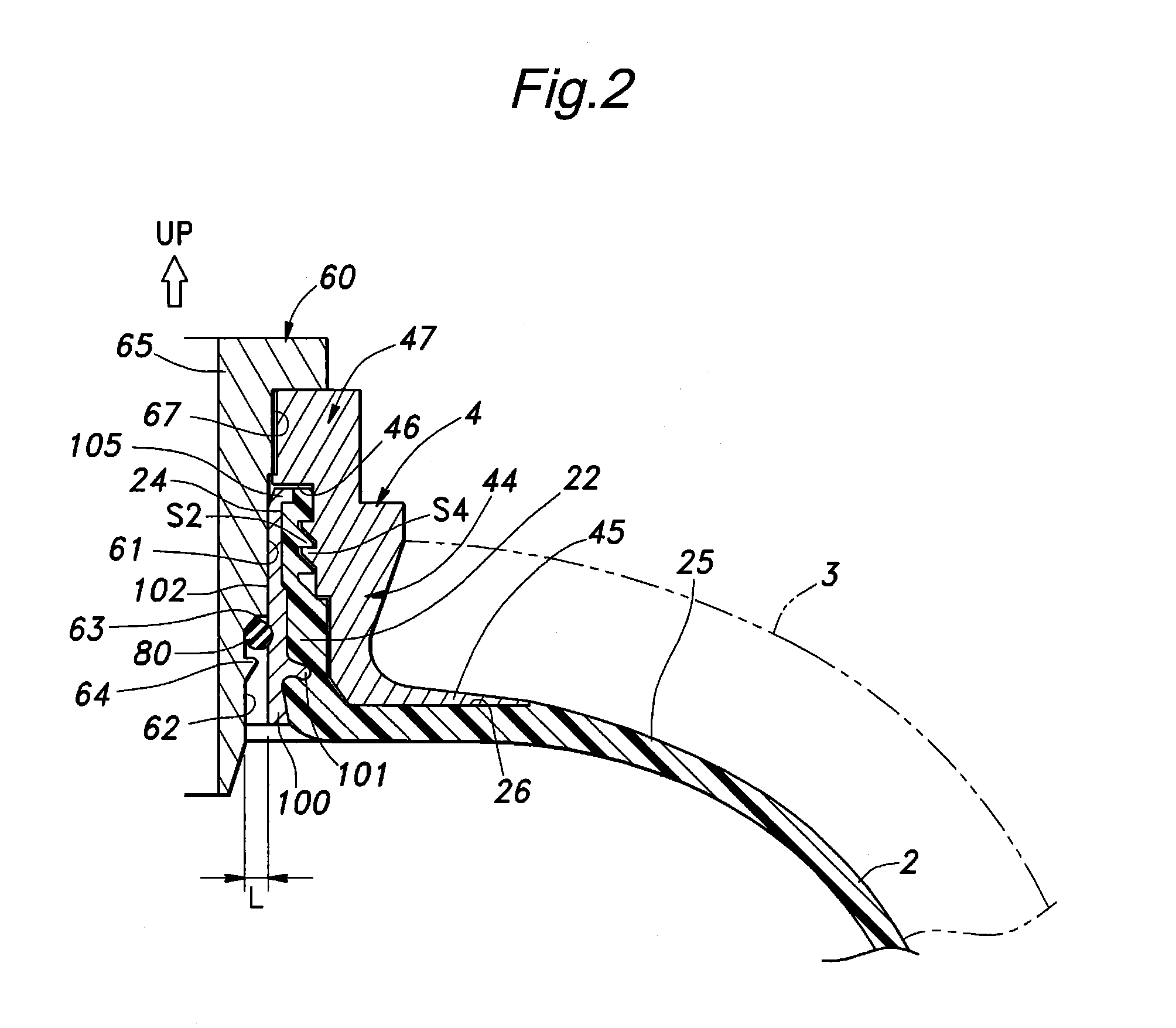
[0042]The tubular member 200 is provided with a pair of annular projections 101 and 103 which protrude into the material of the tubular extension 22. Thereby, the self-sealing feature between the tubular member 200 and tubular extensions 22 and the mechanical attachment between them are even more enhanced. Also, an annular groove 104 is formed in one of the annular projections 103 on the side thereof facing the interior of the resin liner 2 for an improved mechanical attachment and sealing action between the tubular member 200 and tubular extension 22. Such an annular groove 104 may be formed in the single annular projection 101 of the

[0043]Thus, the second embodiment differs from the first embodiment in the modes of sealing (2) the Interface between the tubular member 200 and tubular extension 22 by using a pair of annular projections 101 and 103, and (3) the Interface between the annular shoulder surface 46 of the mouthpiece 4 and the combined end surface of the tubular member 100...

third embodiment

[0047]As a modification of the third embodiment, the tubular member 300 with or without the cover layer 107 may be fitted in the through hole 24 while applying a bonding agent in the interface 108. Any bonding agent may be used, but polyolefin bonding agents are preferred as they provide a favorable mechanical bonding strength and a required air tightness. An improved bonding strength may be achieved by first applying a primer on the surface of the tubular member 300 which is made of metallic material (or has a metallic surface) in this case, and then applying an epoxy bonding agent over the primer. Such an arrangement ensures a secure mechanical bonding between the tubular member 300 and tubular extension 22, and this ensures the sealing performance of the bonding agent. The bonding agent may also serve the purpose of accommodating the difference in the thermal expansion of the tubular member 300 and tubular extension 22.


PUM

PropertyMeasurementUnit
Diameteraaaaaaaaaa
Metallic bondaaaaaaaaaa

Abstract

In a pressure vessel (1) comprising a resin liner (2) provided with a tubular extension (22) defining a through hole therein for receiving and expelling the gas or liquid, a tubular member (100, 200, 300) fitted in the through hole of the tubular extension, a mouthpiece (4) threaded into the tubular extension, a fiber reinforced resin layer (3) placed around an outer surface of the resin liner, and a valve (60) fitted into the central bore of the tubular member, the valve include a section (62) having a smaller outer diameter than an opposing inner circumferential surface of the tubular member defining a gap between the valve and tubular member, and a resilient seal member (80) is placed in the gap. The tubular member is made of a material such as metallic material which is stiffer than the resin liner. Thereby, the resilient seal member is interposed between the tubular member and valve which are both highly stiff or free from deformation when the interior of the pressure vessel is placed under various pressure conditions so that the sealing performance of the resilient seal member can be ensured under all pressure conditions.

Description

TECHNICAL FIELD[0001]The present invention relates to a pressure vessel having improved sealing arrangement, and in particular to a pressure vessel having improved sealing arrangement which is suitable for storing pressurized gas such as compressed natural gas (CNG) under a high pressure.BACKGROUND OF THE INVENTION[0002]CNG is considered as a relatively clean source of energy that helps to avoid the global warming, and is expected to be more widely used as automotive fuel in place of more conventional gasoline. However, gas has a lower density than liquid or solid, and is required to be highly compressed to be stored in a limited space available in a motor vehicle or the like. To store compressed gas, a pressure vessel that can withstand a high pressure is required. Steel and aluminum are typical materials for manufacturing a pressure vessel for CNG. A metallic pressure vessel has the advantage of a high mechanical strength and a proven high reliability, but has the disadvantage of ...

Claims


Application Information

Patent Timeline
IPC IPC(8): F17C1/02
CPCF17C1/16F17C2270/0168F17C2201/0128F17C2201/0147F17C2203/0619F17C2203/066F17C2203/0665F17C2203/0668F17C2203/067F17C2205/0305F17C2205/0382F17C2209/2127F17C2209/2154F17C2209/221F17C2209/227F17C2209/234F17C2221/033F17C2223/0123F17C2223/036F17C2260/011F17C2260/012F17C2201/0109
Inventor TANI, TATSUSHIWATANABE, YOSHIHIRONAKAMURA, TERUYUKISATO, SHOJI
Owner YACHIYO IND CO LTD
Why Eureka
Try Eureka